This simple design makes it possible to change the atmospheric charge. For example, by detecting an increase in atmospheric discharge, the approach of a thunderstorm front can be predicted. The magnitude of the atmospheric charge on a sunny day becomes approximately 100 mV, but with the accumulation of thunderstorms and before rainfall, the magnitude of the electrical charge increases at many times.
During a thunderstorm, the voltage can rise to several thousand volts shortly before the flashlight hits. Here we describe the circuit of the atmospheric electricity monitor, the change of which is displayed on the light scale.
Description of the robotic atmospheric electricity detector
The input lance is combined with an antenna, the signal from which goes to the operational booster DA1 (TL071), which acts as a comparator. This type of operational booster has a JFET input and gain up to 100 dB. This non-inverting input connects to the voltage divider made from resistors R3 and R4, and the input that does not invert connects to the antenna.
Resistor R2 protects DA1 from the extremely dangerous input voltage, while resistor R1 keeps the non-inverting input stable. Since the operational booster TL071 has a very high gain coefficient, then before the addition circuit, resistor R5 creates a reversal connection with the corresponding connections.
Depending on the value of the input voltage, at output 6 DA1 there will be a voltage in the range of 2.5 to 5, which is supplied to the input of 5 LM3914 (DD1) microcircuits through a variable resistor R6. Resistor R7 provides maximum sensitivity.
Material: ABS+metal+acrylic lenses. LED backlight...

Microcircuit is an integrated circuit that is designed to oscillate (linearly) the input voltage and output values to a line of LEDs. In essence, you get a classic analog display on LEDs. The stream that flows through the LEDs is interconnected by the LM3914 microcircuit, which is not necessary for external resistors. This circuit has an input voltage of 1.7 to 4.2 divided into five LEDs.
I'll fix it up
Before the first tightening, turn the knob of the exchange resistor R3 opposite the year arrow, and the exchange resistor R6 approximately to the middle of the range. Give it life and turn the motor of resistor R6 to test the device. The VD2 LED lights up and switches on VD1 for a short hour, which means the correct operation of the device and change the atmospheric charge.
The remaining adjustments will be made on a sunny day with a clear sky, it is necessary for the R4 wrappers to reach the same level as VD5 in order to ensure normal atmospheric electricity. The scheme, despite its simplicity, works very well and allows you to anticipate approaching storms well before the start.
As an antenna, the insulation wires can be insulated for approximately 3 meters, and the ground wire of the circuit can be grounded, for example, to the central firing battery.
Respect! To avoid glare when a thunderstorm approaches, you must connect the antenna to the device.
This device is ideal for those who engage in tourism, hiking, and more. It allows you to record a thunderstorm within a radius of approximately 80 km, which allows you to quickly find protection, seal, and turn on the electrical installation. Retrieving the storm recorder is not so difficult, as there are some missing parts and special adjustments that require adjusting R4 – this is the threshold of the detector’s sensitivity.
Scheme:

The sub-coil L1 promotes its effectiveness. The input circuit L2 C2 is adjusted to a frequency of approximately 330 kHz. L2-wounds on any circuit like an old radio receiver, frame diameter 5mm, 360 turns of 0.2mm, winding height 10mm. The L1 circuit has the same parameters of only 58 turns of 0.2 mm, in my version there is no coil, I replaced it with something else - you can experiment with it.

About the details of a self-propelled thunderstorm proximity recorder. Transistors VT1-VT4 can be anything from KT315/KT361 to KT3102/KT3107. Diode VD1 is a pulse diode.
Principle: By strengthening the transistor VT1, the signal goes to the registering stage (VT2-VT4). The HF pulse turns on transistors VT2 and VT3 and discharges capacitor C4. The current of charging, passing through the diode VD1 and resistor R6, causes the transistor VT4 to become more active and the indicator light VL1 to light up. You can remove the LED or sound indicator from the built-in generator - whichever is better for you. You can check the registrar using an additional igniter - clicking the igniter at a distance from the antenna. It is recommended to ground the device, so there will be greater sensitivity.
Engage a hand-made board in the LAY format:
You do not have access to download files from our server
If you are concerned about the level of static voltage in stormy weather or thunderstorms, then the monitor circuit will help you get started. I was young, mature and was always exposed to such phenomena as the radio-frequency noise of the Earth, as well as the radio-frequency spectrum in the hour of a stormy storm (storm, thunderstorm). I also take into account that since I already have an antenna installed, if I recognize the ever-stronger static field that is building up next to me, then I can immediately react to a possible blow from the flash (for example, ground the antenna). In one of the circuits I developed, I installed a comparator that turns on an alarm sound when the static field strength (V/m) reaches the set value.
I have used a lot of devices, starting with tube ones and finally with designs based on field-effect transistors (FETs) with an insulated gate, but the proposed design has turned everything around for reliability and can provide invaluable assistance in case of problems , more fortune-telling. If you don’t find a model with a zero sign in the middle, I believe that you have others with a zero at the edge of the scale, and by selecting the values of the circuit details, you can adapt to the proposed circuit, whatever your source ruvach, suitable for impedance and flow of permanent arrow injection . Also, you can use other types of field-effect transistors by installing a junction-type field-effect transistor (JFET).
A single-output circuit can be created by adding a oscillator to oscillate the field-effect transistor directly, just do not forget to connect the turn/displacement resistor to the positive pole of the device with p-channel FETs and to the negative pole with n-channel ones.
From this perspective, one of my favorite circuits of all time is the one that uses an n-channel bi-gate FET with insulated gates (MOSFET), such as the 40673, with both gates connected together.
Scheme
In the guidance circuit, the PT gate with the p-channel is connected to the ground wire, so the fragments are bipolarly alive through a very high support, - I was victorious in the first version of 11 Mohm. Remember that such resistors are not only important enough to last, but there is also a problem with them, as there is a big turn in the circuit. In this aspect, most importantly, remove the shutter from the calm and vikorista high-quality new coaxial cable, which is connected to the external antenna, as a rule, with the same considerations. You need to take care of the protection from falling points of the antenna structure, where possible flow of energy to the ground, otherwise you will find that your victor will lose sensitivity to the first drops of the board.

I have installed a 22-inch antenna rod (Wilson) with primary mounting assemblies with two nuts on the end to secure the antenna and with a plastic parasol to protect the antenna design as required. vlogs.
In a similar manner, the coaxial connection may be protected from vologi - here I installed N-type connectors on the antenna and on the chassis for the vibrating device in the middle of the area. Because there is a need for high-resistance resistive voltage, I hope that, if necessary, you can prepare what you need. For high field strength, I chose to use a potentiometer with a 10 MΩ support, which I could, if necessary, turn off in these circuits. For this purpose, I used ceramic insulators with ceramic insulators for high-voltage circuit breakers to reduce the current, as well as cheaper types of wireframes that work poorly. The type of installed PT is not critical - I use the J176 from All Electronics, and also from this company they have “arrived” to a less potentiometer of 10 MΩ and vimiruvach.

As far as life is concerned, then a voltage of 12 V for the AF section is not critical, but bipolarity may be well stabilized and it is important to connect to another transformer or another winding during moderate life, leaving piping wires As a result of the AF IMS, the vibrating circuit will be unbalanced. As a result of the experiment, I discovered that changing the bias voltage of the op-amp provides a more sensitive way of controlling the balancing of the vibrating device, more pleasant, rather than showing the vibrating device in other ways (for example, manually, mechanically, with pointer indicator or electronic balancing (zero setting) - on the dial itself ). Please note that if you cannot get enough of a suppressor with a zero in the middle, then you can ground one of its pins or connect it to the pin of the tuning resistor, where the pin of this potentiometer is connected to the plus and minus nous dzherela zhivlennya, for example, potentiometer support 5 or 10 kO. I tried it and everything worked OK, but I was best suited to the 250-0-250 µA robot. I have not yet developed a good circuit for automatically setting the zero of a vimiruvach, as a rule, the balance is destroyed when the polarity is changed, which can be avoided during spark discharges, as well as in an excessively “peaceful” static field. In the maximum power (sensitivity) mode, you can detect changes in field gradients in clear weather by stretching, as well as thunderstorms in the US state near you. One of the problems that the lightning suppressor circuit suffers from is the need to adjust the frequency of the zero of the suppressor, especially at the position of maximum power, due to the change in voltage polarity during the hour of a thunderstorm.
The analogue multimeter can be replaced by a digital multimeter with a computer interface. The sketch of a Velleman DVM345 digital multimeter is pointed at the baby, which is measured as a transmission to the recording device. (Transient recorder). The software allows you to save graphical displays of values and saves the values from the ".dat" file.

MasView is software for Windows that Velleman hopes to use (http://www.velleman.be/)
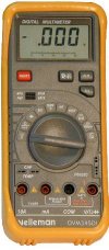
Digital multimeter DVM 345 Velleman with computer interface.
The higher the power of the op-amp, or the higher the input impedance of the PT gate, the more clearly the problem emerges, how I can reduce the impedance of the lanc gate and the strengthening of the op-amp in strong static fields. I also ensured RF access to the op amp and mixed this signal with different levels for static and RF signals, which included adjusting the volume (level).
AF part
The AF signal comes from a simple IC type LM380, you note the interaction of the regulators, so everything will be as shown here. The buffer booster and mixing scheme would have been fine, otherwise I would like to make do with a minimum of details here. A good addition to the output AF circuit would be a bi-equalizer (roughly: tone control), with the help of which it would be possible to formulate the output frequency response of the device and change the level of the transcode, for example, as a background signal.

The image shows an example of an output signal of 0...22 kHz, obtained using additional software from Spectrum Lab Software, developed by DL4YHF). Starting from bottom to top: noise, spherical signals, signals from Alpha project stations, one CW signal and no signals from RTTY stations.
RF part
For the RF part, I repurposed an old low-frequency Tesla coil, which I wound on a plastic pipe 4 feet long and 6 inches in diameter, where I wound 3000 turns of the wire. You can argue that even the direct “motuzkova” antenna works poorly here, it is also pleasant to stagnate the short-circuited elements, so the cat-monster is not at all obligatory here, but I want to take the maximum signals at low frequencies for a high quality factor and cats, so Reduce the intensity of the circuits so that, in your own case, minimize the background of the live current with a frequency of 60 Hz (in the USA, in our country - 50 Hz). Whose senses have long hours, and, especially, the draughts are unimportant here. The signal is amplified by the input op-amp, which is located in its DC storage (JFET), the input selectivity is ensured by the small capacitor size, which allows achieving high sensitivity with a background minimum of 60 Hz. Op-amp type 741 will provide AF amplification, and another op-amp 741 will be used to supply the vibrating head with a 500 µA needle supply (with zero at the edge of the scale) to indicate the level of RF signals. I have to press the brown one in succession with the vibrating regulator in order to install it on the panel together with the power regulator OU 741 in order to live the vibrating regulator, which will ensure the greatest flexibility of the device for all weather minds. This color is even darker to determine the number of lightning discharges per hour during bad weather.
Visnovok
I noted that in a thunderstorm, the release of a great amount of energy in the middle of the gloom, dissolves the appearance of uncontrollable evil streams, which shows that the fields in the middle of the gloom eliminate large masses of water and when the stench, after the discharge, is weaker They cannot wash away water, it spills after impacts intense sparkles, like from a bucket. There is a lot in this, which is already a notorious truth, that I have escaped from a lot of fatalities by reading the immortal works of Mikoli Tesla on this problem and getting stuck with it, realizing that, after all, it’s important to take care of your collections and savings energy and marvel at the result that 'is obvious. what will come out of this?

By the way, the circuit is very simple, it can be found in many variations, and I hope you will find some useful additions to your low-frequency (over-the-head) equipment. It would be useful to introduce ideas into life from the automatic regulation of the zero-setting function of the static electrics, especially since the actual circuit does not destroy significant information about the polarity change, and therefore Light, I agree with almost reasonable ideas from all readers. You will find my email address on my website: http://www.shipleysystems.com/~drvel/, or http://www.bbsnets.com/public/users/russell.clift/index.htm, perhaps -If you want to send it to this site for a sneak peek. I am relying on a new idea from all readers, which is to find projects similar to those previously mentioned, useful.
Russell E. Clift, AB7IF
Exclusive translation from English: Viktor Besedin (UA9LAQ)
For this dispensing water, installed at the ends of the pipes - a dropper, fasten the grille of the room fan (it is necessary to attach the base fan to a high rod). Once a year (or in another algorithm, “programmed” by the radio amator for specific tasks), spray the water supply and tank with fine droplets on the fan blade to wrap it around. In this case (looking at the fact that the fan wraps in one horizontal plane, but can also turn completely up to 90°), a large area of the room is covered.
Every time the frozen aquarium water is dispensed in doses, with small drops, there is no flow of water (and water under the fan). The device was practically tested by the author of the special summer of 2007.
Respect!
The electronic timer, described above, can be replaced with a similar industrial option (and for example), which will be described in section 4.2. In this case, there is no need to independently assemble an electronic device, or, for example, to take a ready-made electronic unit.
1.2. Lightning indicator
Distant thunderstorms disrupt radio communication and navigation, and those that pass nearby can trigger a flashing signal to disable communication equipment.
Particularly dangerous are the direct use of flashlights, which lead to equipment depletion and burn human victims.
Lightning discharges induce strong pulse signals on power lines and connections, and short voltage surges in them can cause malfunctions in work and the failure of expensive electronic devices and computers. The risk of thunderstorms is especially high in rural areas with long open lines, high antennae and radio transmitting equipment, which local radio amplifiers are required to be placed in pagorbi), on poles or metal goldfinches.
Radio equipment should be turned off when there is a nearby thunderstorm.
The approaching thunderstorm is visible and distinct, but how can we avoid warning about it in advance? This is needed by everyone: tourists and fishermen, yachtsmen and radio operators who spend a lot of time on the air. Early warnings about thunderstorms are even more important for other people who work or live far from Ukraine.
1.2.1. Methods for measuring thunderstorm activity in numbers
There are two methods for recording thunderstorm activity. The resentment of the stench was found and research was carried out from the beginning of the 19th century to the beginning of the 20th century.
Static - fixation is ensured by an increase in the electric field strength in the atmosphere from 100 V/m (at emergency conditions) to 1-40 kV/m before a thunderstorm (discharges of flashes are lost and in clear skies). This method is widely known from physics courses.
A device that can record the field strength is called an electrometer.
Today's electrometers do not move folding antennas, register the electrical field of the atmosphere, and thus install the control device on the subcontract, and the electrical field of the front electrified comb made of mixed plastic - at a distance of 1–2 m (in front Newly electrified (rubbed) ebonite stick).
Another method is electromagnetic, in which the field strength is determined by the spectral structure and intensity of radio wave pulses with a frequency of 7-100 kHz, propagated by flashes (discharges).
It is not without reason that this is a sign of a thunderstorm that is approaching, and also a roar of rustling noises (crackles) that are heard by the human ear when listening to signals from radio stations in different ranges of low and medium hvil.
Consider what the Vinaisha method is A.Z. Popov.
This principle is used to control the lightning discharge indicator, the electrical circuit of which is shown in Fig. 1.5.
Small 1.5. Electrical circuit of a lightning discharge indicator
1.2.2. The robot principle will be added
Sub-coil L1, upper (behind the circuit) with any connections to antenna WA1 - width 45-60 cm, increases the efficiency of the input circuit L2C1 of the device. The input circuit is tuned to a frequency of 330 kHz (above the maximum spectral strength of radio wave pulses, which is affected by lightning electrical discharges).
Adjusting the input circuit of the device also means that the location from which you can “spot” a thunderstorm that is approaching. When the elements are marked on the diagram, the device will detect a thunderstorm that is approaching from a distance of 130–150 km (an experiment with a ready-made device was carried out in the village of Yarakhtur, Ryazan region, Shilivsky district in 2007).
Transistor VT1 strengthens the signal to the cascade (VT2-VT4). A high-frequency (HF) pulse (of amplification VT1) with a voltage amplitude of 1-3 is applied to the fact that transistors VT2 and VT3 are opened and the oxide capacitor C4 is discharged. The charging flow of capacitor C4 passes through the high-frequency diode VD1 and resistor R5, which leads to the closing of the transistor VT4 and the ignition of the indicator LED HL1.
1.2.3. About details
Coils L1 and L2 are chokes of type DPM-1, DPM2, DM, D179-0.01 due to the corresponding inductance values indicated on the electrical circuit.
Instead of the HL1 LED, you can use another indicator LED (with a current of up to 12 mA, so that the device is not cost-effective) or a sound indicator (for example, KPI-4332-12 with an additional sound generator oi frequencies). The sound indicator instead of the HL1 LED should be turned on according to the poles indicated on its body.
Resistor R4 sets the operating threshold (sensitivity) of the device.
I will set the life voltage to 3–6 V DC. As a rule, 2–3 AA batteries (accumulators) of type AAA or AA or stabilization adapter are suitable for use with transformer isolation for 220 V.
Since the devices operate at relatively low frequencies, there are no special elements.
Transistors VT1-VT4 can be silicon of low density and similar structure. Instead of VT1, VT3, VT4 you can use KT3102 with any letter index, 2N4401 or similar electrical characteristics.
Transistor VT2 - p - p-p conductivity, for example KT3107 with either a letter index or 2N4403.
Diode VD1 – any pulse type (germanium or silicon), for example D9, D18, KD503.
1.2.4. Nalagodzhennya
The device will not require adjustment (except for setting the threshold for using the changeable resistor R4).
How can I verify it?
Simply check the correct selection of device parts. Bring the finished device with connected living elements 1.5–2 m to a gas stove with automatic ignition. Press the auto-ignition button for a short time. The indicator light is responsible for reacting to short bursts. If there is no stove with automatic igniter, the device can be checked using an additional igniter with a petroleum element. The LED must burn out briefly when the ignition element is turned on at a distance of 0.5-1 m from it.
1.2.5. Options for practical storage
Despite the distant detection of a storm front that is approaching, the device works well at close distances. Thus, you can check the effectiveness of gas stoves with automatic igniters, piezoelectric igniters (for gas stoves - these are the same devices that look like a great stove), and also find out what is wrong with contact in electrical communications - like a closed one placed as well as in the open air. Bad electrical contact, for example, in electrical wiring (radio communication device, which is a source of electromagnetic transients), using a lightning discharge indicator, be located from a distance of a few meters to the point where the worst contact is located deep in the wall.
1.2.6. Industrial devices of similar purpose
Portable lightning indicators (with RKI) have been sold to the public more than once. As a rule, these devices display the speed of approaching thunderstorms, the hour before their arrival, the estimated intensity and other parameters. Alarm system - sound and light. Radio frequency pulses are received via a magnetic antenna, and analysis of their intensity, frequency and spectral composition allows a “smart” electronic device to generate warnings about approaching thunderstorms.
1.3. Linear indicator scale
Most of the descriptions of voltage comparator circuits in which LED bars serve as indicators are based on the principle of parallel equalization of the input voltage (due to the need for a large number of devices in what to equalize – comparators). The number of different devices indicates the number of channels (light-emitting diodes) of the line.
Such a wadi is shown in Fig. 1.6 diagram, with the latest equalization of the input voltage, in which there is only one comparator, which equalizes the constant voltage signal at the input with the transformative voltage, which changes cyclically.

Small 1.6. Electrical diagram of the indicator scale installation
The alignment results are transferred to the storage register on the D2 microcircuit, from which they are read onto the indicator line using a parallel code. This design allows for greater accuracy, precision and dynamic display. Along with other positive advantages of this device over other similar ones - ease of preparation, inexpensive parts, non-criticality to life stress - it competes well for its popularity among radio amateurs and professionals. A variable voltage and pulses can be supplied to the input of the circuit (with a little additional processing) - then it can become a universal, accurate indicator with a light scale that does not compromise on the dynamics of changing the display and accuracy of the page. and equipment with class 2. Linear LEDs have a discrete need to calibrate light scale.
1.3.1. The robot principle will be added
The scheme works in this way. A clock generator based on the popular CMOS microcircuit K561LA7 vibrates direct pulses. The maximum clock frequency of the register at a live voltage is 5 – 2 MHz, U p = 12 V, f max = 5 MHz. You go to the clock input of the register Z of the serial proximity D2, this is the clock input of information that is entered into the register. In parallel with this, the process of adjusting the level of the input voltage behind the additional comparator D3 is carried out. The result of the adjustment (high and low logical level) from the output of the comparator goes to the input D of the data register, indicating the value of its output. After the cycle of converting the input analog signal into a series of logical pulses is completed, the output of the CC register (frame 3) shows an active logical “zero” signal, which is sent to the input of logic D4.1. Elements D4.1, D1.3 are vibrated by the pulse pulse. Therefore, the supply of pulses to the clock input is not captured by the register, and the light scale of the register indicator registers the levels reached by the input signal. The low rhubarb that stops is taken from the output of the Q1 (another young discharge), since one LED line of ten LEDs is installed. If you sequentially install three lines for each LED or a line with 12 LEDs - they are connected sequentially to the outputs Q11 - Q0 of the register. Then logic elements D1.3, D4.1 are turned off, and pin 3 (CC) is connected to the outputs of register 14 (St), and as a result, the sequential proximity register operates continuously, cyclically.
The number of signal equals that are indicated can be increased by adding microcircuits - registers and scale indicators. Such devices are widely used in industrial automation for scientific indication of dynamic processes. I am installing a circuit in a car as an indicator of engine speed (tachometer).
1.3.2. Options for practical storage
A light-emitting diode scale can be installed in a car, on the control panel, to indicate the on-board voltage, the level of the fuel in the tank, the engine temperature, the excess temperature, etc. The scope of this scheme may be rich in advance.
1.3.3. About details
One LED line ALS361A can be replaced with ALS361B, ALS362P, KIPT03A-10ZH (ready for light) – 10L (light green), folded with two lines like ALS345A (8 indicator iv) or ALS345A (8 indicators). Or instead of the LED line, install ten LEDs of the AL307BM type or similar ones.
1.4. Anti-theft devices
Anti-theft systems, according to wealthy retailers, are the most reliable among all types of security systems that are installed in practice at large and small retail outlets. The devices effectively provide greater reliability of the anti-theft tag (due, in particular, to the high intensity of the pulses supplied to the antennas). However, with the ever-advanced acoustic-magnetic technology (EAR), the creation of devices whose impulses flow negatively onto a person (with frequent and severe influx) is mainly due to tension. The low specificity of acousto-magnetic systems is discussed below.
1.4.1. Distinctive features of anti-theft systems
Anti-theft systems today can be installed at every point of sale. A stench can be heard from the sight of two open chairs installed in parallel. Between these flat “thieves” people leave the store (shopping area).
In Fig. 1.7 shows a photo of the anti-theft system.

Small 1.7. External view of the anti-theft system
If the buyer does not carry special microtags with the goods, the “gate” lets him through quietly. If the mark on the product is not removed (not neutralized), the alarm system will sound and alert the sales area with loud alarm sounds.
Then the funeral will be avoided, and the “nesun” will never be caught.
Acoustomagnetic technology is developed by Sensormatic. Later, having become more successful with this technology, the Tyco concern added this company. Nini is a product (and a trademark) of ADT (American Dynamics Technology). On the active devices themselves (antennas, electronics units), copyright is not extended (the term for patents has ended). Another vibrator has also appeared - the WG company.
1.4.2. The robot principle will be added
The anti-theft gate is equipped with a variable receiving antenna that operates at a frequency of 58 kHz with possible variations of ±200 Hz. During the hour of operation, the antenna generates pulses with an amplitude of 40, a frequency of 1.5-1.7 ms (with a frequency of 58 kHz). The pulse repetition period is 650-750 ms.
A greater field strength is created near the antenna, which causes the amorphous metal to resonate at the frequency of resonating.
Respect!
This magnetostrictive effect is even more dangerous for cardiac pacemakers.
At a pause (650-750 ms), the antenna itself begins to receive. The severity of the initiation of the mark changes exponentially over the years according to the complex law that manufacturers keep secret. Therefore, it is difficult to receive a signal from the telephone. However, there is little evidence - such signals greatly interfere with the functioning of the system. It is clear from practice that if there is another store with a similar system 50-100 m away from a store (shopping hall) in which there is an acousto-magnetic system, the smells create mutual interference, which is important to avoid. Advertising producers confirm that their technology is effective and safe (how could it be otherwise?), but it is less likely that it will help (not in vain) to carry out experiments to train the infusion of the most intense (even short-term) impulses for the health of the people.
To understand that this is an amorphous metal, it is important to look at the labels themselves, which sellers put in product packaging.
In Fig. 1.8 shows an acoustomagnetic mark.

Small 1.8 Acoustomagnetic tag of the anti-theft system
The skin of us has grown many times and will always be trimmed in our hands and sore. Let's try to rouse ourselves - the stench has been overcome.
♦ If you remove the anti-theft label from the packaging of the product and look at it from the reverse side, you can apply a metal lubricant behind the visible plastic.
♦ When you cut the mark, you can pull out 3 metal strips: two from an amorphous metal (the smell is more glittery) and one from a primary ferromagnetic strip.
In Fig. Figure 1.9 shows the internal installation of acousto-magnetic tags.

Small 1.9. Internal installation of acousto-magnetic tags
1.4.3. About Skoda, healthy people. Practical recommendations to live a little longer
Acousto-magnetic electronic devices among all anti-theft systems are the most harmful to human health. Ultrasonic frequencies, which are transmitted by their antennas, can be equalized with the frequencies of other biologically active frequencies. The peak tension of the vibration may be reduced to kilowatts.
Work out the tricks yourself.
In case of any emergency, when passing through the “security gate”, be sure to keep your eyes open (so as not to lose your dose of stimulation), and keep your eyes peeled, if the alarm system has sounded (a strong alarm signal), be sure to leave the area immediately by pouring in the antennas, and then by sweating m figure it out the reason for the “activation” of the alarm.
It's a pity, you can often make the picture look better. For example, a special alarm is generated when a frail woman passes through the “gate” of the EAR system. The buyer, sensing an alarm signal, wondering about the reasons for such respect for her electronics, stands at the “gate” and checks that the funeral will begin before her. For the entire hour she is under intense pressure, the influx of which is fundamentally uninhibited on the human body.
These recommendations are based on another aspect: make sure to go through this gate as soon as possible if security forces you to search for an active tag that is located here on the product that you have purchased. The best decisions can be shown to them all the purchased speeches, and the passage of these speeches through the gates is sealed.
1.4.4. Methods to combat EAR
How can you suppress the commercial EAR system?
It's absolutely possible. Zokrema, the way to point to the system is to switch codes from other devices.
Today, many readers have access to the Internet, where you can easily (for free) find out the electrical circuit diagram of the EAR anti-theft suppressor system. To do this, so that the alarm does not turn on when passing through the “gate” with a purchase, for which (for various reasons) the acousto-magnetic tags have not been removed (neutralized).
I will not discuss legal matters regarding wine at the store for unpaid purchases (I myself will not introduce the EAR suppression scheme). More important than that. There is a way to add anti-theft alarm to the “voice”, but not to replace the wasteful influx of electronics into the human body - the buyer, when leaving the store (shopping floor).
1.4.5. How to fix the vibration
For a radio operator who wants to independently examine the problem and find the best solution, I recommend independently recording the changes in the anti-theft systems described above.
For this purpose, you need to take a special sensitive device with you to the store, for example, a signaling device - an indicator of high-frequency vibration from the Master Kit NS178 set.
1.5. A simple sound signal, keratinized with a logical zero
Connecting the sound alarm with a connection to the life-saving device is not always acceptable, especially since the sound alarm must be coupled with another electronic device that forms a logical zero pulse that it controls. In this case, keep an eye on the sound alarm. This decision is justified by the fact that the device for forming the audio signal is assembled on one K561 series microcircuit (using CMOS technology), and the current flow does not exceed 10 mA.
In Fig. Figure 1.10 shows the electrical circuit of the sound alarm.

Small 1.10. Electrical circuit of the sound alarm
At the entrance to the device, you can set the contact button to switch. According to the circuit (Fig. 1.10), the logical zero signal is connected to the output of 1 microcircuit DD1 and the leading edge.
The button produces a logical zero signal from 1 microcircuit DD1.1.
The circuit consists of an infra-low frequency generator on elements DD1.1, DD1.2 (there are 4 pulse microcircuits with a frequency of 0.5 Hz) and a pulse generator with a frequency of 1 kHz on elements DD1.3, DD1.4.
When a signal of a low logical level is displayed on the output of 1 element DD1.1 (when the security loop is broken), the generators begin to operate, and the first generator controls the work of the other, at the output of the node (11 DD1.4 microcircuits) packets of pulses vary in frequency.
The output signal from the output of 11 DD1.4 microcircuits can be applied to the input of other circuits or a booster transistor cascade, or, in turn, to a piezoelectric capsule or (as a result of stagnation of the booster greater sweat zhnosti) on the dynamic head.
The device is more practical and universal. The sound alarm can be installed in security devices, toys, radio communication (for example, as a sound generator for the “transmission” signal and tone signal) and in other applications.
This electronic university is not required.
The lifeline is stabilized with an output voltage of 5-15 V.
1.6. Simple radio pager
A pager is a device that transmits a signal (in short, an alarm signal). In this case, the prefix “Radio” means transmitting a signal via radio channels. There are a lot of current alarms provided by the radio pager device, before the key fob - annunciator - receives the radio signal. Ok, cars have such alarms.
Today you can buy almost everything. Those who have a day, as a rule, are so afraid. Those who want to make money with their own hands engage in creativity. For the creative types of radio enthusiasts, I am presenting on the pages of the magazine a simple electrical circuit of a radio pager - a device that transmits an “alarm” radio signal to a distance of up to 0.5 km in direct line of sight. The owner of the car, which has such a device, is absolutely free (closed, on the New Year’s Day) from the warm bed to the “click of the alarm, behind a sound similar to mine.” Those who have repeated the recommendations of the devices, there is no need to sort out “your own or someone else’s car is asleep”, sensing the danger of clutter packages, as a rule, a standard car alarm signal. The autopager signals directly to your home, without disturbing your blood vessels with sharp trills.
Let's take a look at the electrical circuit of the pager, shown in Fig. 1.11.

Small 1.11. Electrical diagram of a radio pager
The pager transmission consists of a high-frequency generator and booster. Generator for transistors VT1 and booster for transistors VT2.
Transmission of a stabilization pager by a quartz resonator, which operates on the third harmonics of quartz 48 MHz (144 MHz).
Circuit C4, L1 is adjusted to the other harmonic of quartz, circuit C5, L2 – to the third harmonic.
Coil L1 contains 8 turns of PEL-1 dart with a diameter of 0.3 mm, coil L2 - 4 turns of the same dart. Thus, the diameter of both coils is 4 mm.
As an antenna WA1 for installation, a copper high-conductor wire (with insulation) is 30 cm long. For these purposes, it is good to use the MGTF-1.0 wire.
At point A (dif. Fig. 1.11), you can send a signal to external devices (alarm sensors and others). It is important here that the signal at point A is composed of pulses of sound frequency that can be heard by people (100-1800 kHz). This “alarm” signal will be broadcast on air whenever there is an emergency situation. Practical options are discussed below.
Intermediate resistor R4, capacitor C1, which smoothes out pulsations, and the zener diode VD1 acts as a voltage stabilizer for the car generator during engine operation. It is clear that the device will operate as a battery or a stabilized power supply, whose elements can be switched off within the circuits.
The latching button SB1 "ON" turns on the radio pager in the wake-up mode. The device will now broadcast a radio signal when the contacts of the SB2 button are closed, which is the standard light switch (which is activated when the doors are opened).
1.6.1. Nalagodzhennya
The adjustment is carried out with the RF booster turned on (temporarily disconnect the connection point of the collector of the transistor VT1 and the transition capacitor C6).
Primus closes the contacts of the SB1 button, supply life and check the generation on the collector of transistor VT1. If the elements are correct and the devices are properly connected, they will not require adjustments.
This device is ideal for those who engage in tourism, hiking, and more. register a thunderstorm The radius is approximately 80 km, which allows you to quickly find the location, lock, and turn on the electrical installation.
Retrieving the storm recorder is not so difficult, as there are some missing parts and special adjustments that require adjusting R4 – this is the threshold of the detector’s sensitivity.
Sneaky cat L1 advancesїї efficiency. The input circuit L2 C2 is adjusted to a frequency of approximately 330 kHz.
L2-dangle on any circuit like an old radio receiver, frame diameter 5mm, 360 turns of 0.2mm, winding height 10mm. The L1 circuit has the same parameters of only 58 turns of 0.2 mm, in my version there is no coil, I replaced it with something else - you can experiment with it.
The board is designed for the LAY format.


About the details of a self-propelled thunderstorm proximity recorder. Transistors VT1-VT4 can be anything from KT315/KT361 to KT3102/KT3107. Diode VD1 is a pulse diode. The principle is: transistor VT1 amplifies the signal to the register cascade (VT2-VT4). The HF pulse turns on transistors VT2 and VT3 and discharges capacitor C4. The current of charging, passing through the diode VD1 and resistor R6, causes the transistor VT4 to become more active and the indicator light VL1 to light up.
You can remove the LED or sound indicator from the built-in generator - whichever is better for you. You can check the registrar using an additional igniter - clicking the igniter at a distance from the antenna.