The pinpointer is a device that belongs to the family of metal detectors. It is used to search for metal objects in a variety of conditions, including under water. The name of the device comes from English pin pointer, which translates to "dot pointer". The simplest pinpointer is small in size, similar to a pocket flashlight. It may well be useful for finding hidden electrical wiring in the wall.
Purpose of the device
The pinpointer is a metal detector. It determines the exact location of the metal at a rather shallow depth, approximately about 5 cm. People looking for coins or other valuables made of metal, even archaeological, are called treasure hunters. They work with the pinpointer in a wide variety of places: from official excavations to waste dumps. Factory models of metal detectors are not always convenient for such purposes, and besides, they cost a lot of money. Therefore, it makes sense to assemble your own pinpointer according to the scheme. The device is most effective for use in a newly formed pit or dump of soil. The soil can be scattered over a dense volume of grass or large amounts of foliage, making routine searches difficult for treasure hunters. Knowledgeable and experienced people say that in this situation a pinpointer is the best choice.

Parts for assembly
To assemble a pinpointer with your own hands, you will need certain tools. The main elements will be:
- Soldering kit: a certain amount of tin, solder and the soldering iron itself.
- A versatile set of screwdrivers or a set of bits for the screwdriver handle base.
- Clamping tool: pliers, pliers. Cutting: wire cutters or similar.
- To assemble a printed circuit board, you need to stock up on profile material.
It is worth noting that for different models during the assembly process, the list of required materials and tools may also change. Also, basic skills in the manufacture of such boards will be useful, knowledge in the field of electrical engineering and experience in it are welcomed.
Pinpointer schematic diagram
The fundamental provisions of the device model are in the following parameters:

When assembling a pinpointer with your own hands, it is necessary to take into account the basic principle of its operation - the level of measurement quality of the oscillatory circuit. When a metal object approaches it, a loss of power energy occurs. As a result of this process, the signal amplitude on the circuit decreases.
To increase the sensitivity of the device in the assembly, it is better to use film-type capacitors C2 and C3. The radiating element ZP-1 must be piezoceramic.
Assembly technology
The process of making a pinpointer with your own hands is not complicated in itself, but it will still require certain skills in working with SMD components. Another option would be a DIP output element. A ferrite rod that can be removed from an unnecessary transistor receiver becomes a sensor. The rod should be about 110 cm long and 10 mm in diameter. The reels are wound on the principle of superimposing one on top of the other. The material for it should be a wire in an insulating winding. The wire must be copper with a diameter of 0.3 mm. The required number of turns should be 200 pieces.
Particular attention should be paid to the polarity of the connection in a homemade pinpointer. In the absence of generation, at a frequency of 15 kHz, you need to change the extreme points of any winding. Coil characteristics (such as length, wire, rod diameter) can be varied. But it is worth remembering that it will directly affect the sensitivity of the device.
The pinpointer is adjusted by selecting the voltage in the area of \u200b\u200bthe second pin of the microcontroller itself. This must be done using a trimmer resistor R2. At the time of adjustment, there should be no metal objects around the device. This will maximize the effective sensitivity. A voltmeter will help in measurement. This requires a device with a high level of resistance, such as an oscilloscope.

Electronic frequency pinpointer
How to make a pinpointer in this version will tell you how the frequency counter works. The assembly diagram will not cause much difficulty. The operation is based on the operation of an electronic FM frequency counter. There is discrimination of ferrous metals, the depth of the search for objects is limited to 60 cm, the operating frequency is at 19 kHz.
All the required parts are simple and affordable. Little attention needs to be paid to capacitors, which must be thermally stable. These can be the K71 models from the old Soviet multimeter. It is not recommended to use ceramic, they will not work.
Important! The stability of the device directly depends on the quality of the capacitor!
The power source for the pinpointer can be batteries or other rechargeable cells with a voltage of 9-12 V. The printed circuit board itself will need only 10 mA, the rest will be "pulled" by the speaker, an alternative to which can be headphones.

Analog pinpointer
A DIY analog pinpointer is quite easy to assemble. Its effectiveness lies in finding small items, such as coins.
Capacitors for this type of metal detector for the generator are selected of a film type. The voltage must be 100 V or higher. The contoured coil can be mounted on a ferrite rod, the diameter of which should be 10 mm. You can also use a rod from a magnetic antenna built into old radios. The nominal length of the rod should be 10 cm. For winding in a coil, an enameled wire is taken and wound in 4 layers. After completing this process, it is necessary to carry out the procedure for treating the coil with a special varnish in a homemade pinpointer. Finally, the coil will need to be crimped with heat shrink tubing.
Introduction
For a long time I was tormented with clarification of the find in the ground, since my metal detector has a large coil, and finding a small object spent a lot of time on its detection. Finds such as buttons, small crosses and coins-scales are small, sometimes to catch, you had to sift more than a dozen handfuls of earth. And if you went out to hunt at night, the situation is even more complicated. Whoever cops old times will understand me perfectly. To reduce the time it takes to detect an item already found, diggers use additional devices - point metal detectors (pinpoiters). The name comes from the bourgeois word - point-point. When the Great USSR suffered its collapse, our domestic manufacturer was no longer up to the development of point metal detectors, although there were already industrial metal detectors of domestic production by that time.
What is a pinpointer. The same metal detector but with a narrow directional coil wound on a rod.
Commercially available pinpointers cost a lot.
Pinpointer Minelab PRO-FIND 25 - 6500p
Pinpointer Garrett Pro Pointer
- 6200p
Also on the Aliexpress website there is a Chinese podzebka under Garrett for2000 RUR Judging by the reviews, the people are unhappy.
The circuit is very simple, only 3 transistors, the most important thing is that it does not require any settings and starts working immediately after assembly. The power supply is 2 AA 1.5 V cells, in my case - a 3.7 V li-ion battery. Signet.
The diagram shows a number of transistors for the master oscillator, I personally used kt3107 and kt3102, they are in almost all radio stores, it will not be difficult to find them. Film capacitors are recommended, I did not experiment and installed them as recommended by the author. C1 and C3 2 consecutive 1n 100 or more volts. If you take it with a voltage lower, a breakdown is possible, since the voltage on them can grow close to 100 volts. Any diodes can be installed, the planned red glass can be pulled from old boards. Polevik, I personally put bs108, it will show better results than 2n7000 (like on the forum). You can experiment and find an even better one, it is important that the gate opening voltage is 0.8-1.5 V)
Coil


The coil is dangling on a ferrite core, 5-6 cm long, 8-10mm in diameter, 500-600 turns with 0.4mm wire, at the end of the rod, it is desirable to concentrate more turns, from the chuyka it will be higher. I took ferite from an antenna with a conductivity of 800, perhaps a ferite with a higher conductivity will show better results. According to the plan, the frequency on the coil should be within 15 kHz, I measured it with a cartoon, and it turned out to be 14.5 kHz. The frequency increases with a decrease in the number of turns on the coil, as well as with a decrease in the value of c1 and c3. It is not recommended to increase the frequency by decreasing the number of turns, this will make you feel worse. At the end of the winding, I filled the coil with epoxy under vacuum in a 10 cc syringe body, which will allow it to work in unfavorable weather conditions.
Indication
 As an indication, the author proposed to use an active buzzer, an element that you have seen more than once on old motherboards, or electronic alarm clocks. An active buzzer differs from a passive one in that it already contains an audio frequency generator and, when the power is connected, observing the polarity, it begins to squeak. The passive one just clicks like a regular speaker. If you come across a passive buzzer, you can assemble the circuit below, and you will have an active one \u003d)

Also, as an indicator, you can use an LED, a vibration motor from a 1.5v mobile phone or an unknown huergu.

customization
After collection, it should start working immediately, tuning is carried out with a variable (you can adjust the chuyka) or a trimming resistor, setting the response threshold of the field operator (maximum chuyka without going into interference. C4 must be at least 50V. (See diagram) With a well-assembled and tuned device, the chuyka should be about 5 cm for a coin of 5 kopecks of the USSR.If the chuyka is lower, check your coil, 500-600 turns should be wound with high quality.C1 C3 - film, with a voltage of at least 100 V. Also, a large accumulation of rosin or flux in frequency is not allowed - driving part.The frequency on the coil is about 15 kHz.


Features of the scheme.
When turned on, it goes into interference, after being brought up and abruptly removed from a metal object, it stabilizes. (The reason in my case is the too close arrangement of the elements, in particular of the unknown huerga, to the coil.)
After warming up for 10 seconds, you can set the chuyka higher, if set earlier, it will go into hindrances. (In my case, the reason is probably the same)
Unstable work - a chuyka falls (problems among forum participants where this device is discussed)
The frequency and soldering are normal, but the sensation is low - there may be problems with the field worker. Opening parameters 0.8-1.5v.
The coil beeps very weakly and subtly.
In the cold, the chuyka drops a little, but when using a variable resistor it is easily adjusted.
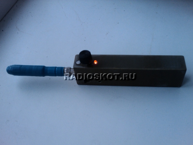
In the field, the device showed itself perfectly. Stable detection of scales - 3 cm, coin 5-6 cm, cross 6 cm. When detecting at night, it is simply irreplaceable, it saves a lot of time for finding a find. At the end, as expected, video of the test)
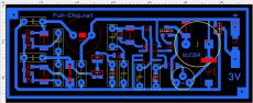
The circuit of a fairly simple analog pinpointer is for people who are looking for coins, but cannot afford to buy a professional pinpointer. I collected this sample personally and confirm its full performance. I spread a printed circuit board specially for him, which can be found at the end of the article. According to its characteristics, the pinpointer is not bad enough, for target designation of a find it is ...
MINIMAX-PP-2 pinpointer circuit

according to the diagram, I think there will be no questions, all the elements are signed on the printed circuit board, pay attention to some details on the board do not converge with the circuit, since I bred it to match what was in the local radio store !!!
All capacitors that are used in the generator must be film capacitors with an operating voltage of at least 100 volts.
Regarding the loop coil L1, I wound it on a piece of ferrite rod with a diameter of 10 mm. from the magnetic antenna of the old radio. The length of the rod is 10 cm. I wound the coil in 4 layers with an enameled wire with a diameter of 0.35 mm. the number of turns is 450. after winding, I soaked the coil with zaponlak and squeezed it with a heat-shrink tube from above.
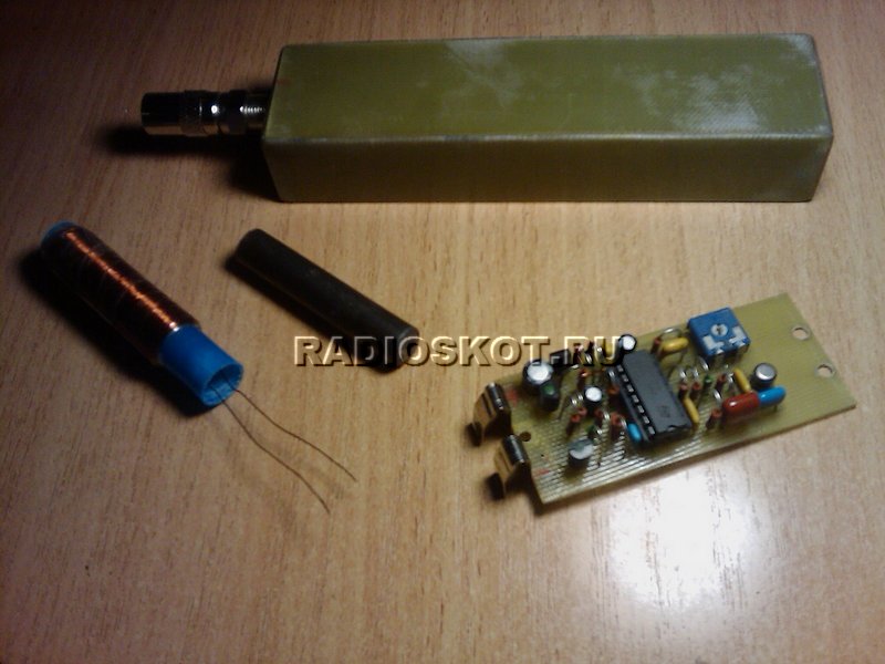
As for the printed circuit board, it is one-sided with the use of both dip and smd components, a buzzer is not just a speaker, but a speaker with a generator!
And finally, a few photos of the assembled board.


Soon I will post a short video with the operation of this pinpointer
Download schematic and PCB file
They are quite different. It should also be borne in mind that devices of this type have their own sensitivity. The main element of the pinpointer is the coil. It is installed most often of the orthogonal type. However, in this situation, much depends on the accuracy class of the device. In order to assemble a simple pinpointer with your own hands, you need to familiarize yourself with the known configurations.
Model with two-wire capacitor
To make this type of pinpointer with your own hands, you must first prepare a case for the device. To do this, many experts recommend using a regular flashlight. The main problem at this stage is finding a good modulator. As a rule, a non-linear analog is selected for a two-wire capacitor. The coil itself must be located in the front of the device. Batteries should be installed behind the modulator. You can also remove them from the flashlight. The minimum battery capacity must be 200 mAh. This is quite enough for 25 minutes of continuous work.
Using three wire capacitors
It is quite difficult to make a pinpointer with three-wire capacitors with your own hands. The modulator in this case is only suitable for the linear type. Nowadays, finding it in electronics stores is not easy. It should also be borne in mind that the coil must be installed under the amplifier. Some additionally equip devices with zener diodes. They are ideal for increasing the sensitivity of the model. Batteries in this situation can be used as standard from a flashlight.

Interruptable Model
To assemble this type of pinpointer with your own hands, you must first take the body from the flashlight. The modulator must maintain a minimum threshold frequency of 200 Hz. All this will allow the sensitivity of the device to be maintained at a high level. This device is used quite often as a tester. To activate the interrupt mode, a regulator must be installed in the structure.
Most often it is used button type. In this case, it is necessary to pay attention to the features of the housing that belonged to the flashlight. It is better to choose a simple coil for this purpose. However, it must withstand the input limit voltage at a level of 15 V. All this will improve the accuracy of the readings.
Modification "Kid-FM2"
It is quite simple to assemble the "Kid-FM2" pinpointer with your own hands. The specified device differs in that its sensitivity is low. However, the prime cost of the model is extremely low, and this device is ideal for home use. The modulator in this case is of a non-linear type. It is mounted directly next to the regulator.
Most often, it is the rotary counterparts that can be found on the market. The inductor can withstand the input threshold voltage at a maximum of 10 V. It should also be noted that this device has a high current conductivity. This was achieved by installing a zener diode. Further, to assemble the "Kid-FM" pinpointer with your own hands, you need to solder the capacitors. Only then are the contacts connected to the Zener diode. At the end of the work, it remains only to fix the batteries in the case.

Pinpointer on low sensitivity transistors
You can make a low-sensitivity pinpointer with your own hands on transistors thanks to a device such as a beeper. It is installed in the housing immediately behind the modulator. The amplifier for this device is only suitable for the pulse type. In this case, the capacitors for the device can be selected different. However, they must withstand the minimum input threshold voltage at a level of 5 V.
It should also be noted that Zener diodes are installed in devices quite often. Their limiting frequency is welcomed at 200 Hz. It is important to take into account that the accuracy of the readings depends on the transmission width of this element most often does not exceed 3 microns. Batteries for the model are selected with a capacity of no more than 600 mAh. This is enough for the device to work continuously for 30 minutes.
High sensitivity model
How to make a pinpointer with your own hands of high sensitivity? To understand this issue, it should be understood that the coil required for assembly is quite powerful. It must maintain a minimum threshold voltage at a level of 20 V. It should also be noted that modulators in this case are only suitable for linear type. The accuracy of the readings also depends on the type of condensate.
In this situation, many experts advise using open-type models. On average, the capacitance parameter for these elements fluctuates around 5 pF. However, in this situation, a lot depends on the capacitor manufacturer. If we talk about a zener diode, then it is used with increased resistance. This is necessary to increase the sensitivity of the device. Batteries for such a model should be selected with a capacity of at least 900 mAh.
Minimax-PP modification
To assemble a pinpointer with your own hands Minimax-PP, you need to choose a PP20 beeper. It should also be noted that vibration mechanisms are installed in devices of this type. At the same time, a variety of indicators are used. If we talk about the coil, then in this case it is used of the orthogonal type. Threshold input voltage of this component must withstand at least 15 V. In this case, the resistance in the circuit should not exceed 4 ohms.
The sensitivity of this device is highly dependent on capacitors. There are two of them in the standard scheme. One of them must be installed near the coil. In this case, the second is attached at the output of the modulator. The main problem of these devices can be considered a small bandwidth of 2 microns. Due to this, amplifiers are rarely used in devices of this type.

Integrated controller device
It is quite simple to assemble this type of pinpointer with your own hands (the diagram is shown below). First of all, you need to choose a good case for the device. At the same time, an integral controller does not take up much space. If desired, it can be purchased at any store with radio equipment, and it costs very little. A distinctive feature of this element can be safely called good conductivity. Capacitors in this case are installed of a two-electrode type. Their resistance parameter on average fluctuates around 2 ohms.
It should also be noted that the coil must be installed first. To do this, you will have to use a blowtorch. Next, the modulator is attached directly. In this case, the rear must contain batteries. In this case, the amplifier is useless. This is due to the fact that the sensitivity of the device is significantly reduced due to an increase in the limiting frequency of the device.

Using multilayer capacitors
The pinpointer is assembled with multilayer capacitors by hand (the diagram is shown below) only in the presence of orthogonal coils. Modulators in this case are suitable for linear and non-linear types. It should also be borne in mind that vibration mechanisms are often installed in devices of this type. At the same time, beepers can be found quite often.
Zener diodes are often used to increase the sensitivity of the device. At the same time, cardiac analogues are especially popular in our time. To install them, you will have to use.In general, it should be noted that models with multilayer capacitors are universal, and are ideal for home use. With their help, a person is able to quickly find out the exact location of the wiring in the wall.

Monolithic board model
It is quite simple to assemble this type of pinpointer with your own hands. These devices differ not only in increased accuracy of readings, but also in good sensitivity. For professionals, this model will work well. It is necessary to assemble the device by fixing the modulator. In this case, many experts recommend using linear analogs.

However, nonlinear modifications are also common. Beepers in this case are installed behind the coil. The parameter of the input threshold voltage of the device should not exceed 20 V. For this purpose, zener diodes are mandatory installed. In this case, the regulators are soldered at will. At the end of the work, it remains only to fix the batteries.
Pinpointer with resonant regulator
To fold the device with the resonant regulator, you need to prepare the blowtorch in advance. First of all, a high-quality modulator is selected for the device. Many experts in this situation still recommend using linear analogs. It is quite difficult to find them in the store, but they should cost little. On average, their conductivity parameter is 3 microns. Due to this, the input threshold voltage can be hoped for at the level of 15 V. Zener diodes for the device are very diverse. They must keep the maximum resistance at 5 ohms. It should also be noted that the device with regulators does not need beepers.
In this case, it is advisable to install the coil last. In this case, the isolation of the wiring must be given special attention. It should also be remembered that the housing of the device must be completely sealed. For this purpose, as an option, you can use a rubber seal. The regulator itself must be soldered to the modulator. Capacitors in this situation are used mainly of the field type. The minimum battery capacity must be 800 mAh.
We would like to present you one of our new developments - a sensitive pinpointer. This device is intended for finding small metal objects. It is used in conjunction with a metal detector during excavation - it is convenient to check the excavated ground for the presence of small coins, as well as to search for metal reinforcement in the walls. Of the advantages, I note the simplicity and repeatability of the circuit, the dynamic combined with the static mode, auto-tuning, high sensitivity, the presence of a VCO - (VCO).Schematic diagram of a homemade pinpointer:

The circuit was tested with a ferrite rod with a diameter of 8 mm, length 50 mm, 320 turns of wire 0.3. Ring with a diameter of 40 mm wire 0.14 - 150 turns. The ground test was carried out with a ring coil. With sudden movements or rotation of the coil around its axis, it reacts to the earth's magnetic field, but this is not particularly annoying, since the search is carried out with smooth movements and without rotational movements.

A flat coil can be made from a fiberglass plate stripped of copper.
The 78L05 integral stabilizer can be replaced with a similar one with an output voltage of 5 volts. If you do not need a VCO (voltage controlled generator), then the resistor R16 must be reconnected to the 12th leg of U1B - shown by a dashed line.

You can replace the transistors of the KT3102 pinpointer with any low-power silicon ones, you can use another sound emitter with a voice coil resistance of at least 100 Ohm, but it is better to put a piezo - it will be economical and loud enough. LED - any super-bright.

This pinpointer is powered by a KRONA 9-volt battery. On the PCB of the pinpointer, there are places for soldering the current collector springs for connecting to the battery. There is also room for a flat coil on the board. Coils in this case can be of any design.

Capacitors C2 and C3 must be foil or others but with zero TKE, other capacitors can be of any type.
The "threshold" control can be omitted, but with it you can increase the sensitivity and also decrease it when necessary. So I recommend not removing it. The pinpointer sensitivity is very high, a small golden ring starts to feel with manual adjustment from 7 cm.
Here is an archive with LAY format, when you hover over an element, the position of the element is highlighted. Sent by Slavake.
Discuss the article PINPOINTER