Currently, there is a lack of different video standards and interfaces. Some have been studying for more than a dozen years, while others are only part of our everyday life and in this diversity it is easy to get lost. It’s as simple as that of non-Fakhivtsevs to apply to the template for the forum. In this article, we have compiled a small selection of various video signal transmission interfaces, as well as expanded video connectors.
We hope that this information will be useful for you.
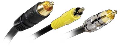
Composite video output
Composite video output of the transmission of one shot of all warehouse video signals in a mixed appearance.
Connect the composite socket either to a standard RCA socket or to a universal universal SCART socket. To transmit a composite video signal, vikorist is used coaxial cable with RCA roses ("tulip") on the ends.
Composite video signal ( composite video) The video cassettes need to be turned on for hours, rather than transmitting a high-brightness signal. For these reasons, only people using inexpensive video equipment, for example, TVs with a small screen diagonal (14"-21"), are victorious.
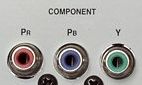
Component video output
Component video signal is also called color video. You must combine the brightness signal (Y) and two color signals (U and V), which are calculated by the formula:
Y = 0.299R + 0.587G + 0.114B
To display the image, you need to use the superintendent ( interlaced) or progressive ( progressive) rosette. Everyone's rosette gets stuck in a row In other systems television communication. The progressive viewer is used in the current TV standard HDTV and in modern DVD players, which allows you to watch more high brightness image
To transmit such a video signal, three wired coaxial cables are used, at the ends of which there are RCA connectors ("tulip") or BNC connectors.
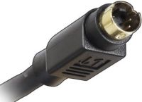
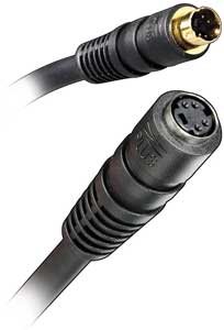
Video output S-Video
The S-Video connector is used to output video signals from video cameras, PCs and game consoles on consumer TVs and other consumer video equipment. The S-Video interface contains two signal lines – the color signal (C) and the brightness signal (Y). When connected to a DVD player or satellite receiver or a 25" TV, this interface allows you to receive a clearer image than a composite video signal.
The cable for transmitting the video signal must be equipped with plugs different types: 2 BNC sockets, 2 RCA sockets ("tulip"), 4-pin Mini DIN socket or universal SCART socket.
Video output RGB
To transmit the color image to the EPT monitor, the signals of the intensity of the skin kvitiv RGB, as well as signals from horizontal (H) and vertical (V) horns. There are five signals output – RGBHV.
To transmit the RGB signal, 5 coaxial cables equipped with BNC connectors are used.
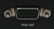
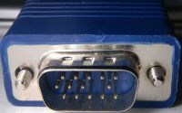
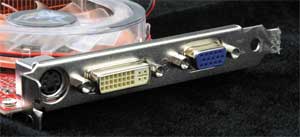
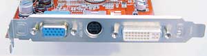
VGA video output
The VGA connector, in addition to RGB and synchronization signals, also provides so-called DDC signals to transmit information between the video card and the monitor. The VGA cable is connected to an additional 15-pin D-Sub connector (also called D-Sub 15 pin).
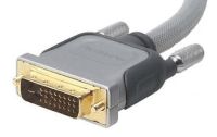
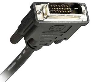
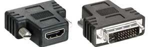
DVI video output
Digital video output DVI is installed mainly in video adapters personal computers. It ensures the transmission of a signal in digital form directly from the video adapter of a computer or laptop to the projector. In this case, the intermediate digital-analog image is not distorted (as with the S-Video standard or composite video signal), which allows you to capture a picture of higher clarity.
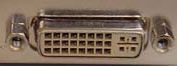
Currently there are two types of DVI connectors:
- universal rose combinations DVI-I. It allows you to connect both digital and analog monitors (with an adapter from DVI-I to 15-pin VGA D-Sub);
- I will add a digital plug DVI-D, up to which digital monitors can be connected. This connector is connected to the DVD-I connector through four openings (contacts) near the horizontal slot. As a rule, such an interface is less common in cheap video cards.
In addition, DVI connectors (DVI-I and DVI-D) support two types of connectors: Single Linkі Dual Link, which affects a number of contacts. In this case, Dual Link uses all 24 digital contacts, while Single Link has only 18. Single Link is used in devices with separate settings up to 1920x1080 (so-called HDTV). For greater flexibility, Dual Link is also used, which allows you to double the number of pixels that are displayed.
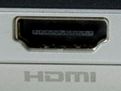
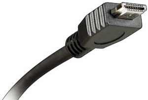
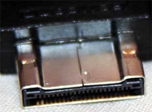
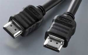
HDMI video output
HDMI interface ( High Definition Multimedia Interface) applications for connecting to DVD players, satellite receivers and video adapters of personal computers, televisions and home theaters. Today it is the standard for transmitting digital audio and video in compressed form.
HDMI is a completely digital format that allows you to transmit not only high-quality video, but also digital audio channels that require only one cable. An HDMI cable with a signal bandwidth of up to 10 Gbps allows you to output a high-quality video signal, and then simultaneously transmit up to eight channels of high-quality audio signal with it.
HDMI interface with a further twist The DVI-D interface and I will go through some details with it, and then go through the detailed parameters.
At this hour it is coming see HDMI rosemiv:
- Type A, which has 19 contacts and the greatest expansion available.
- Type B, which has 29 contacts. This extension has a video channel that allows you to transmit video information from a separate source in 1080p. At this time, we are still not meeting our demands.
- mini HDMI extensions for vikoristan video cameras i portable devices. This includes a variation of the HDMI Type A connector, as well as a change in size.
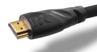
It is necessary to increase the respect that hdmi cable I can’t say goodbye to 15 m-code.
To place all the descriptions of the highest video standards in order of increasing luminosity of the video signal we are streaming:
- composite video
- S-Video
- component video
The article was prepared specifically for the site
Interface S-Video(Separate Video) very often and with unprecedented titles, super-video is most often vikorized in the computer world and until recently was itself manually synchronization of the computer and the TV (here we rely on the analogue ELT TVs). Through this connector, only the video signal is transmitted, as you would like to speed up these connections; the sound will have to be transmitted in some other way, or otherwise acoustic system. The use of the computer's S-Video socket can also be used by rich people. analog devices, such as VCRs, video cameras, DVD players and also riches of others.
All these new roses will appear. Currently, the most popular is the new 4-pin mini DIN connector. In the S-Video interface, a brightness signal and a color signal are transmitted simultaneously through separate cables, which ensures Krascha yakistost pictures, even when transmitted over one cable, for example, with a composite interface, which is one of the advantages of an S-Video connection. In addition, when transmitting via S-Video, the vicor uses less filters and thus results in increased signal intensity.
It should be noted, however, that the difference in image quality will be noticeable even with the large diagonals of televisions, starting with 32”. Also, being universal, this method of transmitting a signal is by removing the SCART connector. In conjunction with expanded digital interfaces, this type of connection will be needed more and more. It is recommended to become a vikorist Danish method connection only in cases where there are no other options (which happens very rarely), the same idea SCART is still more convenient and functional, and when it comes to connecting a computer, and you have an LCD or plasma TV, please use VGA or HDMI interface.
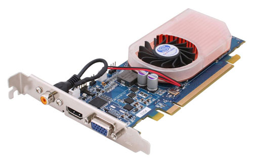
Many video cards provide several (two) outputs, so you can use several displays at the same time.
Since yours is not the oldest for 2004, then, after all, there may be one. Most video cards with DVI outputs come with adapters that convert the signal from DVI to VGA/D-Sub. Also, owners of analog EPT monitors will not be embarrassed. All provide two DVI outputs, which allow you to connect two displays and expand the capabilities of the device Windows desktop. Moreover, the two displays are supported by a combination of DVI and D-Sub/VGA. For new displays with a large diagonal and separate area, for example, for 30" and , a dual-link DVI output (Dual-Link) is required, which supports the "right" separate area of 2560x1600.
Composite video output "tulip", also output as an RCA (Radio Corporation of America) jack.
A traditional video output that is seen everywhere on TVs and other video devices, such as VCRs. The video signal is transmitted through a single coaxial cable. As a result, we can detect a low-quality analog signal, which is used only for presentation or gaming purposes. It is difficult to read from a TV connected through the tulip, since the brightness is very low. However, “tulip” is suitable for standard definition video.
S-Video (S-Video stands for "Super Video" or "Super VHS") is another analog video interface being developed by the television industry.
On the TV it gives the same low-quality signal as the “tulip”, but the color information is distributed over three channels, which correspond to the basic colors. As a result, we receive a clearer signal, less composite over one cable, and, as before, a low dynamic separation. If I want to change the “tulip” yoke, the standard is greatly compromised by the component output (Y, Pb, Pr).
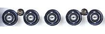
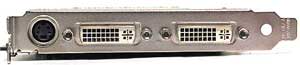
Composite video output RCA and S-Video
The components must be large enough to display them on the video card, so an adapter must always be installed. Select the adapter that provides (the first three video card slots) and sound (the remaining two video card slots). Tsey standard transmits three separate roses of video cards of the “tulip” type: “Y”, “Pb” and “Pr”. They will provide separate color information (high-quality TV station). This type of connection is also found on many digital projectors. Although the signal is transmitted in analog form, its capacity can be fully matched with the high-definition VGA interface. High definition video (HD) can be transmitted through the component interface.
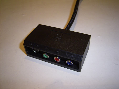
S-Video and three composite video outputs.
HDMI stands for "High Definition Multimedia Interface"
This is a single interface that ensures the transmission of video, audio and information over one cable. bov razroblenie for TV and cinema, ale i computer koristuvach Can rely on HDMI to watch high quality video.
On video cards they appear even rarely, but in the future they may become more popular. Viewing high quality video through a computer can be done either on a video card with HDMI output or on a monitor with HDMI support.
Today's computers have a wide range of video capabilities, and their users often watch movies on the monitor screen. And with the advent of barebone multimedia platforms, oriented toward the market as a home media center, interest in connecting audio to video equipment will only increase.
Where is it easier and more practical to watch the video on to the great screen TV, moreover, almost all modern video cards are equipped with a TV output.
The need to connect the TV to the computer also arises during the editing of amateur video. As you can easily get used to in practice, the images and sounds on your computer are completely different from what you will later hear and hear on TV. Therefore, all video editors allow you to view the latest results of editing on a TV receiver directly from the operating screen before the film is created. Experienced video enthusiasts consistently monitor images and sounds by displaying them on a television screen, rather than on a computer monitor.
Such as adjusting video cards, choosing an image standard, as well as equalizing the brilliance of video outputs of video cards from different video processors and the number of problems that arise from this are beyond the scope of this article - here Let's take a look at the new food: what roses can be seen on TV and on the video card, as they work with each other and find ways to connect a computer to a TV.
Interfaces for connecting a display
Classic analog interface (VGA)
Computers have long been using the 15-pin analog interface D-Sub HD15 (Mini-D-Sub), which is traditionally called the VGA interface. The VGA interface transmits red, green and blue (RGB) signals, as well as information about horizontal alignment (H-Sync) and vertical synchronization (V-Sync).
All modern video cards support such an interface or provide it with an additional adapter from the universal combined DVI-I interface (DVI-integrated).
Thus, you can connect digital and analog monitors to the DVI-I connector. The DVI-I to VGA adapter is included with large graphics cards and allows you to connect older monitors with a 15-pin D-Sub (VGA) plug.
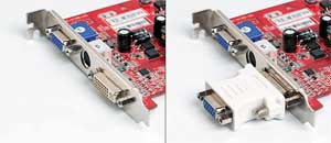
Please note that any DVI interface supports analog VGA signals, which can be received through similar adapters. Any video card supports the DVI-D digital interface, up to which it can be connected only digital monitors. Visually, such an interface is divided into DVD-I with four openings (contacts) near the horizontal slot (align the right parts of the white DVI connectors).
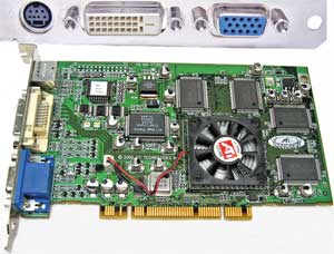
Often, modern graphics cards are equipped with two DVI outputs, and they also have universal DVI-I outputs. Such a video card can be used instantly with any monitors, both analog and digital, in any set.
Digital interface DVI
The DVI interface (TDMS) is the main component for digital monitors, which does not require a graphics card to convert digital signals to analog.
As the transition from analog monitors to digital continues to take place, graphics vendors will begin to use technology in parallel. In addition, current video cards can be used with two monitors at the same time.
The universal interface DVI-I allows for both digital and analog connections, while DVI-D is not digital. However, the DVI-D interface tends to rarely work these days and tends to become more static than with cheap video adapters.
In addition, DVI digital connectors (both DVI-I and DVI-D) come in two varieties - Single Link and Dual Link, which involve a number of contacts (Dual Link uses all 24 digital contacts, while Single Link - less than 18). Single Link is suitable for installation in devices with separate premises up to 1920x1080 (all separate HDTV premises), for about Higher resolutions require Dual Link, which allows you to double the number of pixels that are displayed.
Digital interface HDMI
Digital multimedia interface HDMI (High Definition Multimedia Interface) developed by a whole range of great companies - Hitachi, Panasonic, Philips, Sony, etc. ). To transmit video signals of various types, 29-pin type B connectors are required. In addition, HDMI can provide up to eight channels of 24-bit audio with a frequency of 192 kHz and may new mechanism for protecting copyright Digital Rights Management (DRM).
The HDMI interface is clearly new, but in the computer sector it has a lot of competitors - both from the traditional DVI interface and from new and progressive interfaces, such as UDI or DisplayPort. Products with HDMI ports are gradually being introduced into the market, while today's consumer video equipment is increasingly equipped with HDMI connectors themselves. Thus, the growing popularity of multimedia computer platforms stimulates the emergence of graphical and motherboards with HDMI ports, no matter what computer makers To comply with this standard, you have to purchase a license and pay fees for fixing the license for every product sold with an HDMI interface.
License payments result in higher prices for devices with HDMI ports for an end-cap video player - for example, a video card HDMI port costuvatime for about 10 dollars. more expensive. In addition, it is unlikely that the delivery package includes an expensive HDMI cable (10-30 dollars), so you will end up buying it. However, there is hope that due to the growing popularity of the HDMI interface, the size of such markups will gradually change.
The HDMI interface uses the same TDMS signal technology as DVI-D, and there are inexpensive adapters for these interfaces.
And the HDMI interface has not yet replaced DVI, such adapters can be used to connect video equipment behind the DVI interface. Please note that HDMI cables cannot be extended beyond 15 m.
New UDI interface
At the beginning of this year, Intel announced a new digital interface, Unified Display Interface (UDI), for connecting digital monitors to a computer. So far, Intel has only announced the development of a new type of connection, but in the near future it plans to completely use the old analog VGA interface and begin connecting computers to information display devices via a new digital interface UDI, recently developed by engineers of this company.
The creation of a new interface is due to the fact that the analog VGA interface and the digital DVI interface, according to Intel representatives, are now hopelessly outdated. In addition, these interfaces are not supported new systems depending on the content with which to be equipped digital wear new generation, such as HD-DVD and Blu-ray.
Thus, UDI is practically an analogue of the HDMI interface, which is used to connect computers to modern HD TVs. The main (and perhaps the only) feature of UDI over HDMI will be the presence of an audio channel, so that UDI will only transmit video and will be responsible for working with computer monitors, and not with HD TVs. In addition, Intel may not want to pay licensing fees for HDMI devices, so UDI will become a viable alternative for companies trying to reduce the cost of their products.
The new interface will integrate with HDMI, and will also support all types of content protection systems, allowing you to seamlessly create new media with copy protection.
New DisplayPort interface
Another new video interface – DisplayPort – has recently received praise from the company, which is included in the stock of the VESA (Video Electronics Standards Association).
This DisplayPort standard has been developed by a number of great companies, including ATI Technologies, Dell, Hewlett-Packard, nVidia, Royal Philips Electronics and Samsung Electronics. Coming to the prospect of DisplayPort to Stan UNIVITY DISTRIVE INTERPHIS, PIDKLECHITS DIPLICHICH RIZNIKH Type (plasmovi, RIDKRISTALICHICH, EPT-monitori that IN) before the motive of the spitting of the comporal surgery.
The DisplayPort 1.0 specification provides one-hour transmission capability to both video and audio streams (whose sense new interface completely similar to HDMI). It is significant that the maximum building capacity The DisplayPort standard is set to 10.8 Gbit/s, and transmission requires a thin cable with several conductors.
Another feature of DisplayPort is that it enhances content protection functions (similar to HDMI and UDI). The security measures in place make it possible to display a document or video file only on a number of “sanctioned” devices, which theoretically reduces the incidence of illegal copying of copyrighted materials. And they are installed, different, and updated to a new standard, thinner than current DVI and D-Sub connectors. This DisplayPort can be used in small form factor applications and can easily work in high-channel devices.
Dell, HP and Lenovo have already voiced support for the DisplayPort standard. Obviously, the first devices equipped with new video interfaces will appear until the end of the streaming doom.
Video on graphic card
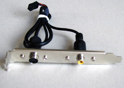
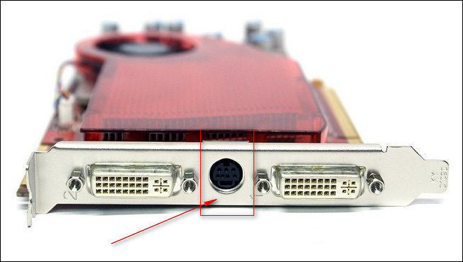
On current video cards, in addition to connectors for connecting monitors (analog - D-Sub or digital - DVI), there is a composite video output ("tulip"), or a 4-pin S-Video output, or a 7-pin combo innovations video output (both S-Video and composite inputs and outputs).
In the S-Video market, the situation is simple - we sell S-Video cables or adapters for other SCART type connectors.
However, if video cards have a non-standard 7-pin connector, then in this case it is better to save the adapter that is included with the video card, since the standard wiring for such a cable is a splint.
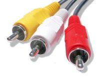
Composite video (RCA)
Thus, composite video output has long been widely used for connecting consumer audio and video equipment. This signal connector is called RCA (Radio Corporation of America), and is popularly called a “tulip” or VHS connector. Please note that such video equipment plugs can transmit not only composite video or audio, but also a variety of other signals such as component video or high-definition television (HDTV). Make the forks of the “tulips” mark with color markings, so that the buyers can more easily navigate the tangle of wires. The expanded meaning of colors is indicated in the table. 1.
Table 1
|
Vikoristannya |
Signal type |
|
|
White and black |
Sound, left channel |
Analogue |
|
Sound, right channel |
Analogue |
|
|
Video, composite signal |
Analogue |
|
|
Component brightness signal (Luminance, Luma, Y) |
Analogue |
|
|
Component color signal (Chrominance, Chroma, Cb/Pb) |
Analogue |
|
|
Component color signal (Chrominance, Chroma, Cr/Pr) |
Analogue |
|
|
Pomarancheviy/Zhovtiy |
Digital audio SPDIF |
Digital |
The wire for transmitting the composite signal can be left long (to extend the wires, simple adapters can be connected).
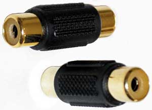
However, the vikoristan of the low viscosity is connected and the low commutation “tulips” gradually emerge at the end. Moreover, cheap RCA connectors on the installation often break. Today, digital audio and video equipment increasingly uses other types of switching and transmission of analog signals using SCART signals.
S-Video
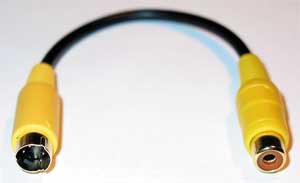
Often, video cards and TVs have a multi-pin S-Video connector (Y/C, Hosiden), which is used for transmitting high-capacity video signals, even composite ones. On the right is that the S-Video standard is vikory different lines to transmit brightness (the brightness signal and data synchronization is indicated by the letter Y) and color (the color signal is indicated by the letter C). The range of brightness and color signals allows you to achieve the finest picture brightness combined with a composite RCA interface (tulip). Higher luminosity when transmitting analog video can be provided by separate RGB or component interfaces. To receive a composite S-Video signal, use a simple S-Video to RCA adapter.
If you don’t have such an adapter, you can create one yourself. However, there are two options for outputting a composite signal from a video card equipped with an S-Video interface, and selecting the type of video card. Each card switches between output modes and sends a simple composite signal to the S-Video output. In the mode of supplying such a signal to S-Video, you simply need to connect the contacts that send a composite signal to the tulip's outputs.
The wiring of an RCA cable is simple: the central conductor supplies the video signal, and the outer braid is the “ground”.
The S-Video layout is as follows:
- GND – “ground” for the Y-signal;
- GND – “ground” for the C-signal;
- Y - brightness signal;
- C - signal of color (to take revenge on color).
If the S-Video output can be used in the composite signal supply mode, then the other contact of this connector is supplied with “ground”, and in the fourth - the signal. On the detachable S-Video plug, which will be needed to make an adapter, the contacts are numbered. The sockets and plugs are numbered in a mirror manner.
Since the video card does not support the composite signal output mode, it will have to mix the color and brightness signal with the S-Video signal through a 470 pF capacitor. When disconnected in this way, the signal is sent to the central core, and the “ground” from the other contact is sent to the braiding of the composite cord.
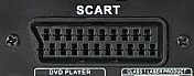
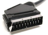
SCART
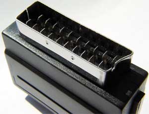
SCART is the most widely used combined analog interface in Europe and Asia. Its name is similar to the French acronym coined in 1983 by the Syndicat des Constructeurs d'Appareils, Radiorecepteurs et Televiseurs, SCART. This interface accepts analog video signals (composite, S-Video and RGB), stereo audio and control. Today, in Europe, TVs and VCRs are equipped with at least one SCART connector.
To transmit simple analog signals (composite and S-Video) to the market, there are many different adapters for SCART. This interface is manual not only because everything is connected using just one cable, but also because it allows you to connect high-quality RGB video to your TV without intermediate encoding in composite or S-Video. Signals and remove the brightest image on the screen of a consumer TV (the brightness of the image and sound when supplied via SCART clearly exceeds the brightness of any other analog connections). Such capability, however, is not realized on all VCRs and televisions.
In addition, the developers have placed the software in the SCART interface additional possibilities have reserved a few contacts for Mayday. And since the SCART interface has become a standard in European countries, many new authorities have emerged. For example, with the help of active signals on pin 8, you can change the TV modes via SCART (switch it to monitor mode and back), switch the TV to the robot mode with RGB signals (pin 16), etc. Pins 10 and 12 are used for transmitting digital data via SCART, so it is practically impossible to operate a number of commands. There are a number of remote systems for exchanging information using SCART: Megalogic, developed by Grundig; Easy Link from Philips; SmartLink from Sony. However, their installation is limited to the combination of TV and VCR of these companies.
Before speech, the standard transmits four types of SCART cables: type U – universal, which ensures all connections, V – without audio signals, C – without RGB signals, A – without video and RGB signals. Unfortunately, daily component modes (Y, Cb/Pb, Cr/Pr) are not supported in the SCART standard. However, manufacturers of DVD players and large format TVs make use of the ability to transmit via SCART and the component video signal that is transmitted through contacts that correspond to the standard for the RGB signal (however, when connecting RGB, this is also possible does not disturb).
To connect to SCART composite or S-Video devices, a variety of adapters are sold. Most of them are universal (bidirectional) with an input-output switch.
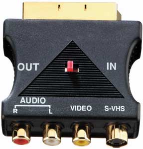
There are also simple single-direction adapters, adapters for connecting mono or stereo sound, as well as connectors for remixing. Alternatively, if you need to connect one device to two at a time, you can split the SCART device into two or three directions. Those who are not controlled or for whom the assigned options are not available can generate power according to the recognition of the SCART contacts indicated in the table. 2.
The numbering of the pins is indicated on the rose:
Of course, computers do not use a SCART connector, however, knowing its specifications, you can now prepare a suitable adapter for connecting an analog computer monitor to receive a video signal from a tape recorder or, to supply a video signal from a computer to a TV, possession of a SCART rose.
For example, to input or output a composite signal from a SCART connector, you need to take a 75 ohm coaxial cable and separate the outer braid (ground) and the inner core (composite signal) to the SCART connector.
Output of video signal from the computer to the TV (TV-OUT):
- the composite signal is supplied to pin 20 of the SCART connector;
To input a video signal from a VCR to a computer (TV-IN):
- composite signal – to pin 19 of the SCART connector;
- "ground" - to the 17th pin of the SCART connector.
p align="justify"> The type of contacts when preparing an adapter for S-Video is also listed in the table. 2.
Outputting the video signal from the computer to the TV S-Video (TV-OUT):
- 3rd pin S-Video – 20th pin SCART;
Inputting a video signal from a VCR into a computer S-Video (TV-IN):
- 1st S-Video pin – 17th SCART pin;
- 2nd pin S-Video – 13th pin SCART;
- 3rd pin S-Video – 19th pin SCART;
- 4th S-Video pin – 15th SCART pin.
To connect a computer to an RGB TV, it is necessary that the computer outputs an RGB signal that is visible to the TV. The RGB signal is supplied through a special 7-, 8- or 9-pin video output combination. Depending on the configuration of your video card, it may be possible to switch the video output to RGB mode. Since the video output on the video card has seven contacts (such a plug is called mini-DIN 7-pin), then in normal mode the S-Video signal is supplied to exactly the same contacts as in the original S-Video connector. And in RGB mode, contact signals can be distributed in different ways Depends on the video card's distributor.
As an example, you can connect the contacts to one of these 7-pin SCART connectors (this layout is installed on some video cards that are based on NVIDIA chips, but on your video card it may be different):
- 1st contact mini-DIN 7-pin (GND, ground) - 17th SCART contact;
- 2nd contact mini-DIN 7-pin (Green) – 11th SCART contact;
- 3rd contact mini-DIN 7-pin (Sync, connector) – 20th SCART contact;
- 4th contact mini-DIN 7-pin (Blue) – 7th contact SCART;
- 5th contact mini-DIN 7-pin (GND, ground) - 17th SCART contact;
- 6th contact mini-DIN 7-pin (Red, red) – 15th SCART contact;
- 7th contact mini-DIN 7-pin (+3 V in RGB mode) - 16th SCART contact.
For all types of adapters, it is necessary to use bright cables with a 75 Ohm support.
There is no connector for connecting video on the graphics card
If you have a daily TV output on your video card, then, in principle, the TV can be connected to the same VGA connector. However, what kind of guy needs it? electrical diagram Usage of signals (at Zagalny Vipadka, It’s true, it’s awkward). There are special devices on the market that convert the original computer VGA signal into RGB and the trigger (sync) signal for the TV. Such a device is connected to a VGA cable between the computer and monitor and duplicates the signal that comes through the VGA output.
In principle, such a device can be developed independently. The type of VGA and SCART signals will be as follows:
- VGA SCART PIN SCART Description;
- VGA RED – on the 15th SCART pin;
- VGA GREEN – on the 11th SCART pin;
- VGA BLUE – to the 7th SCART pin;
- VGA RGB GROUND - on the 13th, 9th, 5th SCART pin;
- VGA HSYNC & VSYNC - on the 16th and 20th contacts of SCART.
It will also be necessary to apply +1-3 to the 16th SCART pin and 12 to the 8th SCART pin to switch to AV mode in a 4:3 aspect ratio.
However, a direct connection, which works for everything, does not work, and for synchronization you will have to work with an electrical circuit, as shown at http://www.tkk.fi/Misc/Electronics/circuits/vga2tv/circuit.html or http://www.e. kth .se/~pontusf/index2.html .
Please note: Before connecting the cable, you must turn on the TV and computer!
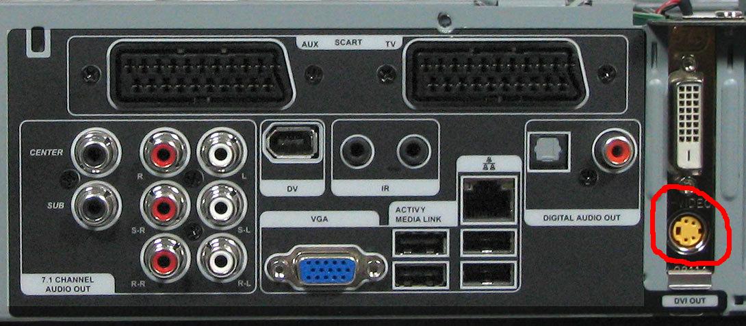
Check what your video card can do
![]() Check what your TV has input
Check what your TV has input
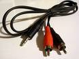 Check that you have a cable S-Video->RCA (S-Video-tulip) and Audio (Jack-2RCA)
Connect the cable to the video card () and jack to audio out, to the TV RCA (A/V tulip plugs) and 2RCA (audio).
Output S-Video– black round 4 and 7 – contact socket, usually located on the back panel of the TV and often used to connect to a new cable TV.
You can connect your computer to your TV in different ways However, the most accessible way is to connect via the S-Video connector. The S-Video connector is present practically on the skin video card, and thus protects the skin, as a matter of fact analog TV. In addition, the S-Video interface will ensure a clearer sound transmission: the clarity of the picture when connecting a computer to a TV via S-Video connectors will be much better than with either RCA or multiple cables connected adapter.
Well, now we’ll look at how to connect a computer to a TV using S-Video connectors.
S-Video input– one of the largest early connectors for connecting to a TV external devices. Who is to blame for the memory of the Radyan televisions: an antenna was inserted into these roses.
This black jacket is best suited for connecting cables for TV and children's game consoles. Today's TVs are equipped with a wide variety of connectors: RCA (tulip), HDMI, DVI, VGA (D-Sub) and, of course, an S-Video connector.
Many owners of current plasma or LCD TVs inevitably “forget” about the S-Video connector, and tend to use more modern interfaces - the same HDMI, DVI, RCA. At the same time, S-Video provides richly improved color transmission and color reproduction.
Perhaps, just for connection LCD TVs(as everyday matrices are similar to computer monitors) it is better to use the current digital interfaces: HDMI and DVI.
And the three-color RCA outputs are nothing less than an original innovation. Composite connections are sacrificed to all advanced interfaces.
Connecting your computer to your TV via the S-Video connector is easy, so you don’t have to mess with adapters. Every TV and almost every video card (even the older models) are susceptible to such roses.
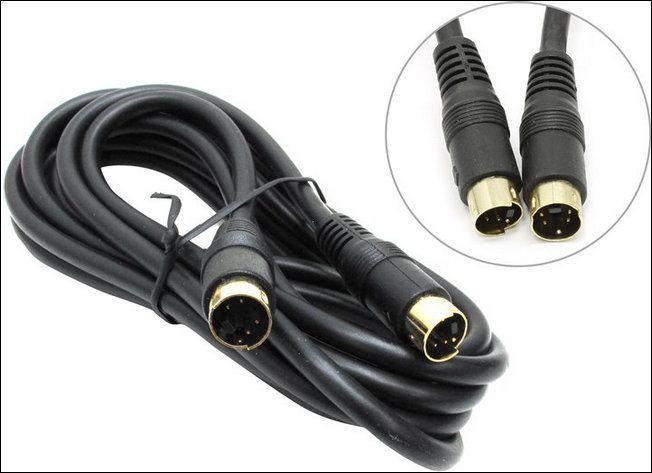
You just need to connect them with a cable. And every store has enough S-Video - S-Video cables. This standard cable is great since the 90s.
Now, we connect the computer to the TV via the S-Video connector.
1. We connect the computer and TV with an "S-Video - S-Video" cable
Before connecting the computer and TV, you must turn it on. If the TV is connected to a cable tower, the cable from the S-Video connector must be unplugged. After that, let's start before we meet.
Insert one end of the cable into the S-Video output of the computer (black “circle” on the video card), and the other end of the cable into the S-Video input of the TV (similar black “circle” on the back (or on the front) panel of the TV izora) . The S-Video output is the connector through which signals are received (in our version, the S-Video connector on the video card), and the S-Video input is the connector through which signals are received (in our version, S-Video connector on the TV panel).
2. We turn on the TV first, and then the computer.
At the moment infatuated with Windows The TV screen is slightly damaged. This step is to confirm that the TV has detected external signals. Hey, our connection is going well. How to Vikorist digital TV, then in this case it is not necessary to switch it to AV mode - the signals must be received from the antenna jack itself (S-Video).
3. Setting up a video card
If the video card is NVidia (Ge-Force), the same is selected. Click here right button on the desktop, select “Power”, open the “Options” tab (on the right upper codend window), click on the “Additional” button for the deposit.
In the window, go to the tab with the name of the model of our video card (Ge-Force****). We put a checkmark on “Clone” (this means the TV is like another monitor), with the left-handed Ge-Force window open, we see nView and click on Apply. After clicking on the “Display” field and from the list of devices that opens, select the name of our TV. The image may appear. You can also enter i here additional adjustment image (coordinated color, for example).
If an ATI video card is defective, the first three lines will become permanent. And after clicking on “Dodatkovo”, the computer itself will tell you how to connect your TV. Installation instructions will appear on the screen. You just need to vacate them.
4. Turn on "search" on TV
Unfortunately, when connecting a computer to a TV via S-Video, the images in the following episodes need to be adjusted, like the next TV channel. To do this, listen and scroll through the frequencies until you hit the computer desktop.
In short, the computer connects to the TV via S-Video exactly like Game console: Connect the cord, and then adjust the image settings.