For those who decide to assemble their own computer from scratch, rather than buying a ready-made system unit, it will be useful to know how to assemble the individual elements correctly into a single workable whole. I present to your attention a guide on how to assemble a computer.
What to buy
The first step is to buy the minimum necessary kit to start your computer
- body
- a source
- motherboard
- cpu cooling system
- rAM
- Video card (discrete not always required)
- hDD
It must be understood that all purchased items must be compatible.
When buying a motherboard and processor, the socket (in other words, the platform where the processor is inserted) on the board and the CPU must be the same. This parameter is always indicated in the technical specifications, for example, Intel Core i3-4130, has an LGA1150 socket, we can easily install it on the ASRock H81M board. You also need to take into account the slot for RAM, at the time of the article's release, the most common DDR3, therefore, you need to buy DDR3 memory.
We start with the case, which will be the “home” for all other components. After unpacking, unscrew the side panel.
We see the ready-made holes for the motherboard fasteners. All you need to do is "try on" the board to the holes and fix it. There are many holes, as some cases are designed for motherboards of different sizes (form factors).


However, before attaching the motherboard, you need to install some elements on it.
Intel processor and cooling system installation
Open the processor socket using the latch shown in the figure. The thing is pretty delicate, you don't need to make much effort.

After opening the slot, pay attention to the processor. In the case of Intel, there is a special edge, and there is a guide on the motherboard that will prevent you from inserting the processor correctly. This greatly simplifies our life, those who are familiar with electronics know how to bother with microcircuits in order to properly solder them to the board. There are, as a rule, no guides on the board, only a point in the corner of the microcircuit showing the first leg.


After installing the processor, we finish the procedure, protecting the socket: we close it in the same way as we opened it before.

The next important step is connecting the cooling system.
A cooler often comes with a purchased processor, if not, the processor manufacturer has a list of recommended ones for connection
Be sure to remember about thermal paste. In some radiators, thermal paste is already applied, if it is not there, then you need to apply
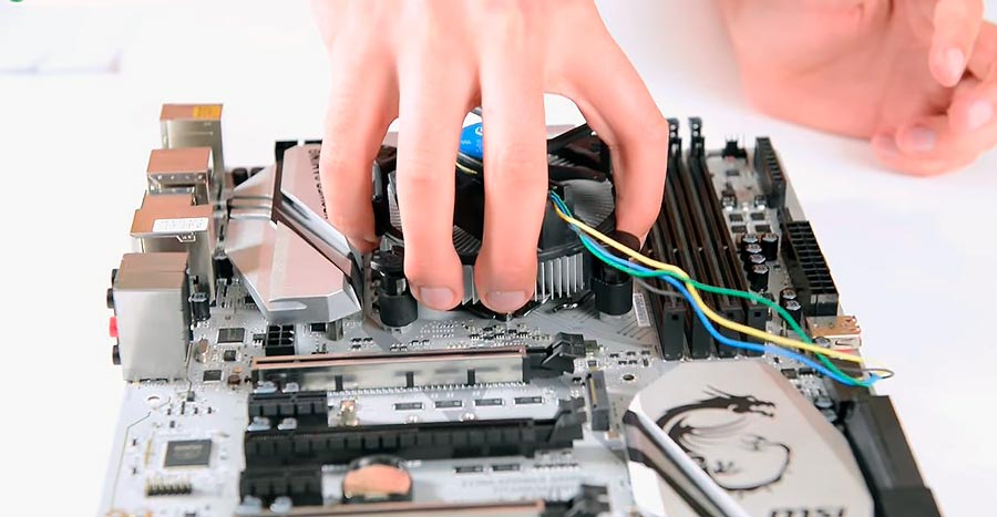
Note that the cooling system is secured with four latches, which should fit perfectly into the holes on the board, in the corners next to the socket. 

Actually, we install it in the holes, and begin to press it without much effort, until you hear four clicks. 


It remains for us only to connect the fan to the power supply system, on the board the connector is designated as CPUF AN, we connect to it) 

If you bought the cooling separately, you decided that the standard is not enough for you. Then you will certainly need to apply thermal paste. Just apply a small amount to the center of the processor and spread it all over the surface, with an old credit card or unnecessary plastic card, precisely fit the surface of the processor and cooler

Note: When buying a cooling system, do not forget to peel off the film

Installing a system with a processor and heatsink - AMD
Consider that in the case of AMD CPU, installing a cooling system 
First, unblock the socket by pulling the metal handle directly adjacent to the edge

The legs of AMD processors are located so that the slot can only be inserted in one way: as in the case of Intel, it is impossible to install the processor differently than the manufacturer intended. Inserted and secured. 
Then we apply thermal paste ... 
We combine the processor planes and the base cooling system

The coolers have different mounting methods, and all of them are indicated in the manual, there shouldn't be any difficulties. In our case, next to the socket we have a plastic base with protrusions. The metal mount is included with the cooling. 

Installing memory (RAM)
The last element that we can install in this phase is RAM.
To do this, you need to find the RAM slots located next to the processor socket.

Before installing memory, you need to check the motherboard manual to find out which slots to install in the first place (if the number of modules is less than four). In our case, these are blue slots. Opening the latches

Insert modules properly


After installation in the memory slot, we return the plastic latches to their original position

At this stage, you should receive a motherboard with a processor, cooling and memory modules. We put everything aside for a while and move on to the case and the power supply.
Installing the power supply
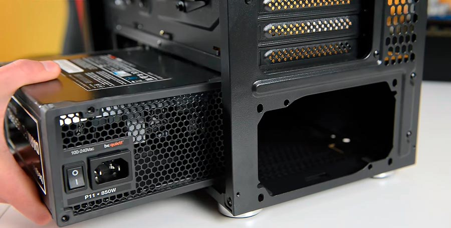
We install the power supply in the lower part of the case. 
We fix it with a fan DOWN.

This position provides him with ideal working conditions: the device constantly has access to cold air from under the case and at the same time excludes the ingress of warm air that is thrown out of it onto other elements, and nothing is additionally heated.
On the back of the case, secure the power adapter by tightening the four screws.

If the power supply does not have removable wires, then we simply pass all the wires through rubber grommets to the back of the case.
If it is modular (detachable cables), then you must first connect the necessary cables, including PCI Express power (for a video card) and SATA (for storage media). 


Only now we pass the entire bundle of wires from the power supply through rubber hoses behind the tray with the motherboard.
Installing the motherboard into the case
We insert the board into the case; there should be a specially allocated space for it in the case. 
We do not put any gaskets and pads, we use only the set that comes with the kit (bolts plus stands) 
Then you need to connect the external USB ports located on the front panel, as well as the Power and Reset buttons, two indicators showing the activity of storage media and power.
First we look for a connector signed as USB, then we connect the plug

And then find the pins (JFP1) associated with the buttons and LEDs, connect them to the connector, according to the marking next. 


Installation media (HDD / SSD)
Speaking of mounting hard drives, again, everything is individual. In our case, we have a rack with a plastic slide. We attach the hard drive to these sleds, and insert into the rack. 


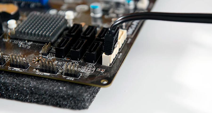
Next, the necessary step is to connect the media / media to the motherboard using SATA signal cables, and also bring power to them.

To do this, find on the board small connectors labeled as SATA. In the instructions for the board, we check which of them are the fastest (SATA 3 - 6 Gb / s), and it is to them that we connect the disk on which we will install the system, especially if the system is installed on an SSD. Other media will fully satisfy the slower speed (SATA 2 - 3Gb / s). 

First of all, we connect the power cable, and then the signal cable
Installing a graphics card
The graphics card is the last item (within the basic configuration) to be installed. 
Look for the first free PCI Express x 16 port (blue, closer to the CPU cooler in the photo below). First, we deal with traffic jams. 99% of currently available video cards require the space occupied by two dies on the back 

As with the slots for memory modules, the PCI Express slot has small protrusions that will prevent you from mistakenly installing the video card. You simply have no choice, you will do everything right. 

Then we fix the video card. 

Connecting power to the motherboard
The motherboard is powered by two wires. One is the 24-pin connector shown in the picture below. Located on the right side of the board, next to the RAM. 
The second power cable is the heart of the computer - the processor. we insert it into the slot located in the upper left corner.

It remains to "feed" our video card. The most power hungry (but powerful) models require two plugs, seen in the picture.


Before closing the case, you need to check the operation of the power button, restart and LED information (the part that tells you that your computer is turned on, and others that indicate the activity of the HDD / SSD).
Outcome
The idea that something is extremely complex in the assembly is erroneous. You really need to try hard to ruin something. Equipment manufacturers care about the convenience of users by introducing physical restrictions: the processor can only be inserted into the socket in one position, it is impossible to connect the power connector in the wrong direction, or to the wrong connector. The worst thing that can happen is that you can forget about any of the cables. But don't worry about that: the computer won't do anything, it just won't start until the wires are properly connected. Good luck!
Assembling a computer is not difficult. Assembling a computer as a designer - all the details fall into place and knowing the theoretical part, in principle, there should be no problems with the assembly. All that is required of you is time and accuracy, since this constructor is often expensive and does not forgive mistakes.
In this article, we will cover the most important aspects and questions that may arise when building a PC. How to assemble a computer and not break anything?
Before assembling a computer, you must be sure that all components are compatible with each other. Checking components for their compatibility is not difficult. If you are not sure yourself, then use the special assembly configurators that are available in many stores. For example, one of these configurators is www.regard.ru/cfg.
By the way, you can find the most suitable assembly for you on our channel in Yandex.
CPU
The contact pad on desktop processors comes in two types: PGA (pins) and LGA, where they have been replaced with contact surfaces.

PGA is used in AMD and older Intel processors. After socket 775 (the place where the processor is installed), Intel switched to the LGA socket. It is extremely difficult to bend or break anything in such a processor, which cannot be said about motherboards for this connector. Manufacturers of motherboards for the Intel socket put a special plug for a reason.
There are a lot of contacts under it, which are called “legs”. Neatness is needed here. If you get dust or dirt, you probably won't get it. The legs are very flimsy. If you bend one of the legs, then it is quite possible mate. the board becomes defective. It's also not worth aligning them yourself. If this does happen, it would be wiser to contact the service center.
The socket must be removed immediately before installing the processor. Check if all the legs are intact, if nothing is bent, and only then proceed to install the processor into the socket.
By the way, the plug on the latest motherboards for Intel processors may not be removed at all.
The locking mechanism is opened using a special lever. The checkbox on the processor and socket must point in the same direction.

He and a pair of keys on the socket and processor are your main reference points. Make sure that the processor is properly seated on the contacts, and only then close the locking mechanism.
He will resist a little, but don't be alarmed. This is normal, the processor frame just presses the processor quite tightly against all legs.
This is not the case with AMD processors. They have "legs" located directly on the processor, and the motherboard connector is made in the form of special niches for these "legs". Make sure that all the feet on the processor are in place and that nothing is bent, and only then proceed to install the processor into the socket. When installing, again, you should be guided by the special markup (checkbox).

Installing AMD processors is easier. Carefully open the socket and place the processor. It should sit completely in the connector.

Cooling system
Perhaps installing the cooler is more complex (relative to installing other components). They often have thermal paste already applied to them. Should it be replaced with something more worthwhile? If it is a budget cooler or a boxed cooler (included) - yes, it is desirable, but not critical. On top-end cooling systems, this will be superfluous.
Before installing the cooler, wipe the surface of the processor. This can be done with alcohol or degreaser.
Read the instructions, do not ignore this step. Install and check that the cooler is secured and not loose. You can grasp it with your hand and lift it up with the motherboard.
With cooling for AMD processes, everything is easier, but we also read the instructions. Install the cooler and fix it with a lever.

The cooling system purchased separately, as a rule, also has thermal paste already applied, but the fixing methods may be different. For tower coolers, for example, you need a special substrate for the processor (backplate), and in the case of AMD processors, it may be necessary to dismantle the native retainers on the board

Tower coolers are usually fastened with screws; the mounting wrench is usually included in the kit. The most important thing when installing such a cooler is not to over-tighten the screws. It should fit snugly against the processor and not wobble, but this does not mean that the screws need to be tightened like a car wheel.

Don't overdo it. After installing the cooling system, connect it to the motherboard - CPU FAN connector.
Thermal paste
It so happens that the paste is not applied to the cooler, but lies separately with it in the box. Then you will have to apply it yourself. The paste is applied only to the metal cover of the processor. The thinner the layer, the better.
The paste is well applied, for example with a plastic card. It is not desirable that the paste gets on the processor substrate. Some thermal pastes conduct electricity and this can cause short circuits.

Just apply some paste to the center of the processor and install the cooler. Under pressure, it is evenly distributed over the processor cover. Sometimes the edges are not smeared, but they do not play a significant role in the heat dissipation process. Read on which thermal paste to choose and how to change it.
RAM
The simplest thing is to install RAM. However, in slots with one-way commit, memory is more difficult to insert. Sometimes normal effort is required.
There is a key in the socket of the socket, there is a notch on the memory card. Open the latch on the slot, insert the model as far as it will go, close the latch. Make sure the memory is flat, especially with one-sided slots.

It often happens that on the side of the lever, the module is not fully inserted. This can lead to the fact that after turning on the PC, the system will not start.
Usually, before installing the motherboard in the case, I check the system performance on an open bench. You may not do this, but it may be useful to someone.
After installing the processor, cooling system, hard drive and RAM, I power the motherboard, processor from the power supply and connect the HDD. Next, I close the connectors with a screwdriver, to which the power buttons from the case are connected. They are usually found on the lower right side of the mat. boards:


Gigabyte

Having checked the system performance, and sometimes having installed Windows at this stage, I proceed to the assembly already in the case
Housing
Now it's time to put the motherboard into the case, but before that it is advisable to install the power supply, otherwise in the future there may be a problem with the neat laying of the wires. Plan in advance what will stand and route the appropriate wires there.
Also, before installing the motherboard, do not forget to install the special socket for the connectors that came with the motherboard on the back of the case. It starts up from the inside of the case and is installed, as it were, by pressing it out.

The board should stand in the case on special racks (hemp), there are from 4 to 15. Don't miss this moment! Matching the motherboard with its approximate location in the case, screw the rack into these holes.

They must be the same height. Check if all the "stumps" are screwed into the body to the same height (to the end). In cheap cases, this can be a problem, and often you cannot do without the help of a tool. The motherboard should not touch the case; it should lie evenly on the racks.

Racks are part of the body kit. It so happens that there are more holes on the board than on the pallet. It doesn't matter, you don't have to use everything. The main thing is to fix the edges of the board and the middle of the board in at least one place.
Storage devices
Connecting the drive is as easy as shelling pears. In the case of a regular SSD (2.5 inches) or hard drive, you only have two wires: the power supply and the data transfer (SATA) wire that comes with the motherboard.

Check the location of the key, if nothing is interfering with their normal connection. The SATA cable is the same. In most cases, the cord has a lock with a lever at the top of the connector. If the cable needs to be removed, simply clamp it down, otherwise the connector on the mat-board may break.

In modern cases, drives are fixed in special sleds. It is very convenient and does not require special screws, unlike budget cases.
Laying wires
Do not allow situations when the power wires or the connector are connected to the device for a kink, you are guaranteed to break the block or the connector on the device itself, especially for drives.
You can not give a damn about the accuracy and stuff all the wires with a lump. Of course, the system will work, but unfortunately. The wires will interfere with the normal air circulation in the case, the system will become dusty faster and will overheat. Plus, there is a possibility that one of the wires can get into the processor fan cavity.
Lead the wires behind the back wall and fix them with cable ties through special lugs.
Case fans
They are usually two in front and one for blowing. Attached to the body with self-tapping screws. Pay attention to the airflow indicators before installing into the housing. If it is the back wall (or the upper part of the case) - the arrow for blowing out of the case, the front one - the air intake into the case.

The fan can be connected both to the motherboard and to the power supply (via an adapter). If the fan has a 4-pin connector, then it must be connected to the corresponding connector on the mat. board, which is designated as SYS FAN. The advantage of the 4-pin connector is that it becomes possible to automatically control the fan speed depending on the processor load.
Make sure that there is nothing in the way of air circulation. The top of the hard drive must be vented to prolong its life.
Connecting the Power Supply
First of all, we connect the most important cables. There are two of them - a 24 pin (or 20 + 4) power cable for the motherboard and a power cable for the CPU 8 pin (or 4 pin). We insert them to the limit, you will hear a characteristic click (not always). Do not confuse 4 pin CPU and PCI-E power supply wires.
Sometimes it happens that the processor power connector on the motherboard has an 8-pin connector, and the power supply cable for the CPU is only 4 pin.

You can connect half of it and it will work, but this is not desirable. Not the fact that your motherboard will survive this.
By the way, this does not apply to video cards and we will analyze why later. If the power supply of the CPU 4 + 4pin is indicated in the characteristics of the power supply, this means that the connector is type-setting, suitable for both 8-pin connectors and 4-pin connectors.
It's the same with the power supply of the board. Power supply 20 + 4 means that your block is suitable for motherboards with a 20-pin slot, as well as for a standard 24-pin one.

The situation with the video card is different. Here, too, there is a type-setting connector for 6 + 2 pins or only 6. In fact, there is only a 6-pin connector. It can be one, two or three, depending on the coolness of your power supply. And it differs from the 8-pin only in the jumper.
Additional 2 contacts do not create a potential difference, these are two zeros. They serve as a marker for the card that your PSU is powerful enough for the card and will provide the required amperage.

Connect the additional ports on the chassis carefully. Do not hurry. There is a key on the connector - be guided by it, make sure that the legs of the connector are even, do not bend them. This is especially true for the USB 3.0 connector. Cases are not uncommon when, due to carelessness, the user bends the leg on the connector or tears it off when he abruptly pulls out the connector. How to connect the front panel of the computer to the motherboard is described in more detail here.
Video adapter
Typically, the video adapter is installed last. Everything is simple here. Insert the video card into the graphics slot and fix it with a screw on the expansion card frame. If the card is wide, it is best to secure it with two screws.

Don't forget about the lock on the slot. It's not for beauty. Before installation, it must be open and only then insert the video card until it clicks. Remove the card only with the release lever. Click on it, and the card will rise in the slot, after which it can already be removed.
Static electricity and methods of dealing with it
Do not collect your PC in synthetic socks while standing on a woolen carpet. Simple cotton gloves can be used, especially when working with RAM modules without heatsinks. Perhaps this is the only detail that is afraid of static. Common sense and compulsory reading of the instructions are your best assistants.
If the computer does not start after assembly, check how you installed the components. It starts, but rather stops working - more likely a problem with the RAM or its incorrect installation.
If it comes to BIOS already well, you can find a possible reason. If the lights on the motherboard light up, coolers are spinning, but nothing on the monitor - check the installation of the video card. Resetting the BIOS or updating it can help.
As you can see, assembling a computer yourself from components is not so difficult. The main thing is to know the theoretical part. We have covered the main points that may come in handy. Naturally, this is not all. There are so many variations of the component and there are so many possible problems. The components should not be mechanically damaged. Before you decide to assemble a computer, carefully check the components for external defects. Good luck with your assembly.
In the first part of a detailed guide on assembling a computer with our own hands, we will talk about installing a processor on a motherboard, installing its cooling system and installing RAM.
Introduction
In recent years, the computer industry has experienced a real boom in the mobile PC segment. The smartphones, laptops, ultrabooks, monoblocks and, of course, tablets flooding the market are increasingly pushing classic desktop computers out of our lives. This trend is also evidenced by all kinds of reports from various analytical agencies.
But ten years ago, everything was completely different. Sales of system units and components for them were the main source of income for many computer companies, and low-power and expensive laptops were practically not regarded by users as an alternative to a stationary home PC.
It is this time that can be called the heyday of "self-assembly", when the overwhelming majority of sold system units were assembled not at branded factories or factories, but in small pavilions of computer markets, by the hands of self-taught sellers. The users themselves did not lag behind. The most creative and experienced of them preferred to independently assemble the future PC itself at home. And I must admit that this approach had many advantages. The individual parts were usually cheaper than the complete computer. Moreover, it was possible to choose a suitable hardware manufacturer, eliminating the possibility of low-quality equipment made by nameless handicraft Chinese firms (it was called “noname”) in your desktop.
Today, self-assembly of the system unit is less and less practiced by users. And this is not surprising. As we have already noted, on the one hand, the desktop PC market is currently in decline due to the rapidly increasing popularity of mobile computers. On the other hand, enormous competition and the development of iT-technologies have made it possible to saturate the market with inexpensive computer devices that make “self-assembly” impractical for the sake of saving money.
And yet there are still many enthusiasts who prefer not only to independently make the configuration and select components for their future electronic machine, but also to assemble all this with their own hands. Moreover, this applies to high-performance computers of the middle and top level. After all, it is this approach that allows you to choose the right balance between the installed devices and their cost, without worrying about the fact that, for example, a powerful processor, you will be installed with a weak video card with a large amount of video memory, which simply will not be used. Also in this case, there are always ample opportunities for the subsequent modernization of the system unit, modding and promptly carrying out minor repairs.
Thus, despite the fact that assembling a PC with your own hands is gradually fading into the background, this issue still remains relevant. Therefore, we decided to prepare material, or rather even a manual for novice users, where it will be popularly described in detail how to assemble a system unit on your own at home.
Before assembly
Before starting the assembly, let's get acquainted with the components that will make up our future computer. It is worth making a reservation here right away that we in no way urge you to assemble a PC of that configuration and from the same parts that will participate in this material. All the equipment, on the example of which the assembly will be demonstrated, is a purely personal preference of one person and has nothing to do with advertising of certain brands and manufacturers.
So, in our case, solutions from Intel were chosen as the main platform of the future computer, which include a motherboard based on the Z77 chipset with an LGA 1155 socket and a quad-core processor of the Core i5 family. A tower fan with a low noise level was chosen to cool the processor.

The rest of the participants in our assembly were: a pair of 4 GB DDR3 RAM modules, a GeForce GTX 580 video card, a 1 TB hard drive and an additional in-case fan for blowing it out, a DVD-RW optical drive, a medium-sized ATX case and a power supply 700 watts
In order to put all this together, we need only one tool - a medium-sized Phillips screwdriver, preferably with a magnetic tip. And of course a couple of straight arms.
Everything is ready to start the assembly and now is the time to remember one important detail - static electricity, which in some situations tends to accumulate on our body. All computer components, with the exception of the power supply, are low-voltage equipment and can easily burn out even from the most short-term high-voltage discharge. But the banal brushing of hair or rubbing against woolen things can lead to the accumulation of a static charge of several thousand volts. So imagine what would happen if you split it into some computer part?
To avoid unfortunate consequences, be sure to touch any metal object, for example, a heating pipe or a refrigerator, before taking on components. If your body was electrified, then in this case, the accumulated charge will be instantly discharged. Also, during assembly, it is better not to wear things that can contribute to the accumulation of static electricity.
The assembly itself should preferably be performed on a non-conductive surface (wood, plastic). If the desktop is covered with a cloth tablecloth, then it is better to take it off for a while, since many fabrics tend to accumulate static electricity.
Installing the processor
At the first stage of assembly, we will install the processor and RAM into the motherboard, as well as mount the CPU cooling system. Of course, you can first screw the motherboard into the case, and only then do the above steps. But here it is important to know that some processor fans have mounts, some of which are located on the back of the "motherboard", which can make it impossible to mount it when the board is already inserted into the case.
Finding the CPU socket on the motherboard is very easy. It has a rectangular shape with side dimensions over 4 cm, so it is quite difficult not to notice it.

One of the main design differences between Intel and AMD processors is the fact that in the first, contact pads are used to connect to the connector on the motherboard, and in the second, contact pins.
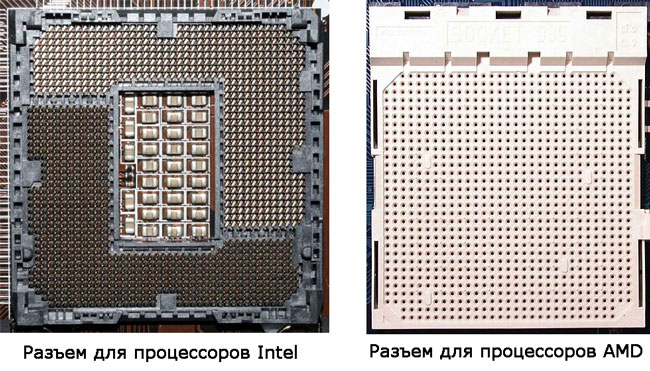
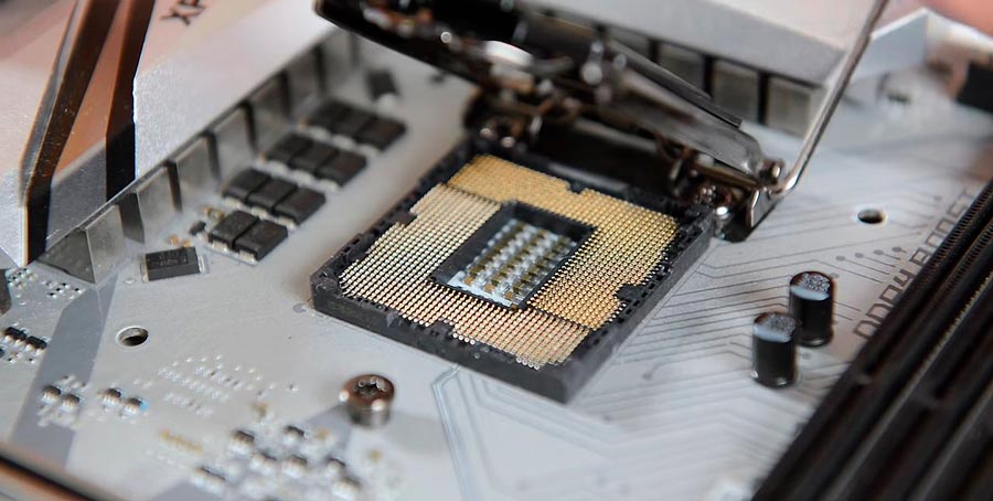
Accordingly, motherboards also have different sockets, which for Intel microprocessors are equipped with soft spring-loaded feet, and for AMD, many tiny holes. Recall that in our case we are dealing with an Intel processor and an LGA socket.
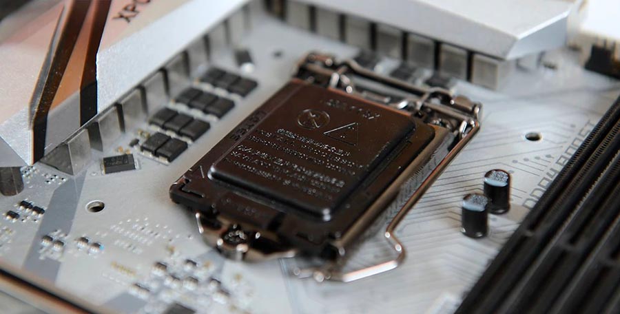
Before installing the processor, you must open the connector by pressing the metal lever and pulling to the side.

After release from the mount, move the lift lever upwards, after which the pressure frame will open.

To prevent incorrect installation of the processor into the socket, manufacturers make auxiliary docking notches in the design of their cases. Intel has semicircular notches on the case, while AMD has beveled corners.

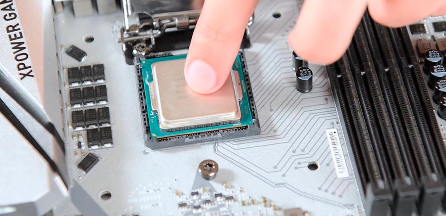
After opening the connector, we take the processor and install it into the socket without any effort or pressing, so that the docking cutouts are aligned.

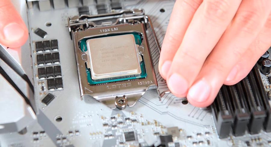
Now we close the clamping frame by inserting a protrusion located on it with a recess for the stopper, and return the metal lever of the elevator to its original place, thereby pressing the processor to the contacts located in the connector.
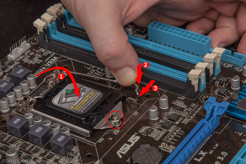
At this point, the black protective cap on the hold-down frame should fly off and can then be thrown away. At this point, the installation of the processor can be considered complete, so let's proceed to the installation of the cooling system.
Installation of the processor cooling system
Today on the market there are a large number of different cooling systems that use different methods of attachment to the motherboard. Of course, it is difficult to tell about all the nuances within the framework of one material, but this is not necessary, because, as a rule, many coolers with unusual mounting systems are supplied with detailed instructions for their installation.
We will consider the two most common methods of mounting fans, which are used with certain nuances in the vast majority of cooling systems.
There are four holes in the motherboard for installing the cooler next to the processor socket.

In most cases, the cooler mount for modern Intel processors contains four legs, which are inserted into these very holes and fixed there by pressing them from above. To avoid distortions, it is better to mount it crosswise.

Standard fan for processorsIntel
To dismantle fans with this kind of mountings, you must turn the head of the leg counterclockwise 90 degrees, then pull it up. After removal, rotate all legs to their original position.
Motherboards with connectors for AMD processors are equipped with a special frame for installing a cooling device, to which the standard cooler is attached with two screws. So everything is simple here.

Let's move on to our case. We did not use the original Intel fan, replacing it with a more advanced low-noise tower cooler. Its installation on the system board is slightly different from the above standard procedures. Here, to increase the stability of the cooler, a special frame is used in its fastening, which is located under the processor socket, to which it is subsequently screwed with screws. We will begin with its placement.

We attach the frame to the back of the motherboard in such a way as to align all four holes on both parts. Then we insert the screws that come with the kit, and fasten on them from the other side of the board, the nuts to which the frame will be attached, pressing the heatsink base in the processor cover.

The processor is cooled by the process of heat exchange between its cover and the base of the cooler. Ideally, the lid and base should be completely flush with each other for maximum heat dissipation. But in practice, this is very difficult to achieve, since their surfaces have roughness. Therefore, in order to increase the contact area, liquid thermal paste is used to fill the microvoids, thereby improving heat transfer between the surfaces of the devices.
As a rule, in many solutions, including inexpensive and standard coolers, thermal paste is applied to the radiator of the cooling system at the factory. So you just have to properly mount the fan to the motherboard. But in our case, the thermal paste will have to be applied independently, since the tube comes with it separately.
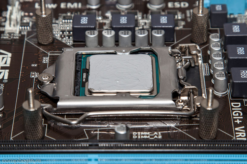
You should be aware that thermal paste should be applied in a very thin layer. The principle, the more the better, is not suitable here, since this will only harm the normal heat transfer. For application, you can use any handy means, for which there is enough imagination. We used a regular cotton swab, after wetting its ends a little so that the cotton does not peel off.
We squeeze a small amount of thermal paste from the tube onto the processor cover.

Then we spread it evenly over the entire area.
Now, everything is ready to install the cooling system. We take the radiator and remove the protective film from its base.

We install the heatsink on the processor and fix it with a special clamping frame and nuts that are screwed onto the screws we prepared earlier. To avoid distortions of the radiator, tighten the nuts crosswise.

Now it remains to connect the fan to the control connector on the motherboard, and then put it on the radiator, after which the installation of the cooling system can be considered complete.
The connector on the motherboard for the processor cooler, always located next to the processor socket, has four pins and is named CPU_FAN.

It should be borne in mind that the cooler itself can often have a three-pin connector, which in any case will be compatible with the one on the motherboard. The presence of the fourth contact is optional, since it is responsible for an additional function that makes it possible to use various automatic modes for adjusting the fan speed, depending on the processor temperature, using the BIOS of the motherboard.
Regardless of which connector you have on the cooler, to avoid incorrect connection, it always contains auxiliary recesses, so it is almost impossible to make a mistake when connecting the fan to the motherboard.
Our first stage of assembly is completed by installing RAM. This is a very simple procedure, as you will soon see for yourself. It is not at all difficult to find slots for installing memory, since they have an elongated shape, are always located next to the processor socket and are painted in pairs in different colors. By the way, they have appeared more than once in many previous photographs.

In our case, we have four connectors of black and blue colors, which makes it possible, if desired, to install respectively four memory strips. In general, different motherboard models may contain 2 (budget models), 4 (standard) or 6 (legacy models) RAM slots. As you can see, in any case, their number is even. The fact is that it is customary to install memory modules in pairs to enable dual-channel mode, which makes it possible to speed up the process of data exchange between the "RAM" and the central processor twice. That is, if you want to have 8 GB of RAM, then you should buy two 4 GB strips. Of course, you can install one 8GB memory chip instead, but this will reduce the performance of your computer.
It is not for nothing that the manufacturer paints the RAM slots in pairs in different colors. These are the so-called "banks" (bank), each of which has its own color. To use the dual-channel mode, you need to install a couple of memory chips in one bank, and not randomly. For example, in our situation, we fill either both black slots, or blue ones.
Before installing the modules, we spread the white locking levers on the sides of the selected connectors to the sides. Then, with a light press, gently insert the memory stick into the connector.

In this case, it is imperative to align the notch on the memory module with the jumper in the connector on the motherboard.

After making sure that the strap fits into the slot, fix it by pressing the memory corners from above until it clicks. In this case, the side latches must return to their original position.

We do the same with all the other planks.
At this point, the first and most important stage of the assembly can be considered complete.

Do not be surprised, but after installing all the above components, you can start the system for the first time and check its performance. After all, most modern processors have an integrated graphics core, and motherboards have integrated connectors for connecting a monitor. Having temporarily connected the power supply of the processor and the motherboard, it will not be difficult to turn on the assembled system by closing the corresponding contacts on the "motherboard" with any metal object, for example, a screwdriver. Only experienced users should do this trick. Well, if this is your first build, then go directly to the second stage.
Sometimes, it happens that the computer that is in the house, due to old age, began to work poorly, or, even worse, just took it and died a quiet and unexpected death. And, perhaps, everything is not so dramatic and the old iron machine is simply tired of its owner, who always strives to keep up with new technologies.
There can be many reasons why there is a need or desire to acquire a new computer. But the question is not even that, but where to get a new computer. Of course, you can just buy it at your nearest hardware store. But, you can assemble it with your own hands, which is much more interesting and, importantly, significantly raises self-esteem. And such a computer will be much more functional than its store counterpart, since the details for it can be selected at your discretion.
Almost every user can assemble a computer on their own. But in order to do this correctly, it is necessary to slightly tighten the theory about computer internals and about what-where and in what order to insert, screw, connect, etc. In addition, the theoretical part will be very useful for those who first decided to assemble a computer. It is in order to prevent such beginners from trembling in their hands and an irresistible desire to find valerian in the closet that this article was written, which is essentially an instruction for assembling a computer, and even with illustrations. Therefore, there is nothing to be afraid of, a screwdriver in hand and go!
What you need to have with you:
· A Phillips screwdriver is longer (you can use a regular one, but it will be more difficult).
· Round nose pliers (pliers).
· Plastic ties or clamps.
· Medicines (for the most suspicious).
Assembling and installing the motherboard into the case
The first step is to assemble all the proper components for the motherboard. The motherboard itself is shown in the figure below. Let's consider its components:
1. CPU socket (socket);
2. Sockets for RAM (their number may be different, 4 are shown here);
3. Connector for a video card;
4. Power socket of the motherboard;
5.SATA connector;
6.Front panel connectors.

These components of the motherboard will be discussed in more detail below, during assembly.
Installing the processor
A processor is a small flat square that has contacts on one side. There are no more similar parts in a computer, so it is rather difficult to confuse a processor with something else.

In order to properly insert the processor into the socket, you must do it in a certain way. One of the corners of the processor has a special triangle mark. Your task is to find this corner on the part, then release the fasteners on the motherboard, find the same corner in the processor socket (socket) and insert the processor so that the designations match.

It is very important to make sure that it is inserted straight before you secure the processor, as trying to close an incorrectly inserted part may damage the processor pins or break them altogether.
Cooler installation

A cooler or, in other words, a fan is installed on the processor. But first, the surface of the processor must be smeared with thermal paste, unless, of course, it is applied to the surface of the cooler.
To make the layer thin, the paste (which should be about the size of a pea) can be spread over the surface using a piece of cardboard or a plastic card. After the processor is lubricated, you need to install the cooler and fix it with special feet, as shown in the picture.

Installing RAM

In the image of the motherboard, the slots for RAM are shown under the number 2. Their number may vary. The RAM strips themselves look as shown in the following picture. In order to insert the RAM into the slot, you need to open the plastic clips that are located at the edges of the slot. Then directly insert the strip vertically until it stops. If the procedure is done correctly, then the clips will snap into place by themselves.
If there are identical ramps, it is better to insert them into slots of the same color. This will make it possible to significantly speed up the computer.
Installing the motherboard into the system unit
After the motherboard is fully completed, you need to insert it into the computer case, which looks like this.

The motherboard is installed on the side wall of the block. Don't worry if you notice that there are more mounting holes in the case than necessary. This is necessary so that you can install motherboards of different sizes.
First, you need to "try on" the motherboard by firmly attaching it to the case. This is necessary to see if the motherboard connectors fit into the protective panel. If everything matches, the motherboard can be fixed. If something does not match, then you need to break off the protective plate with holes using pliers and insert another panel there.

Installing a hard disk, drive, video card
It doesn't take much effort to install a drive or hard drive, the main thing is to know what to connect with. So, to connect a hard disk or drive, the SATA data channel is used, which is shown in the first figure under number 5.

A pair of connection cables comes with the motherboard, so you don't have to look for them. Loops can be connected to any SATA pins.
Since not one hard drive is usually installed, but several, it is necessary to remember one important point. It is best to install hard drives not too close to each other. Usually, the system unit has three or more slots for hard drives. Therefore, you can install one hard drive in the lower cell, and one in the upper one, so that air circulates between them, which prevents overheating of the surfaces of the parts.
If all the cells for hard drives are occupied, then it is advisable to install an additional fan to cool the hard drives, since overheating significantly shortens their service life.

The slot for connecting a video card is in the image at number 3. The video card itself looks like this.

It will not be difficult to connect it, but first, the video card must also be “tried on” to the slot. This is done in order to determine exactly where to insert the card and which plug will have to be removed from the back of the computer. The further process is identical to connecting the RAM: we insert it exactly to the end. The final touch is to secure the video card with a special mount or bolt.
Installing the power supply
The power supply looks like a metal box from which a lot of wires come out. The system unit has a special place for the power supply. Shown below.

The power supply is inserted so that the power outlet and the button are outside, and the bundle of wires is inside.

After the power supply is in place, you need to connect the wires. First we connect the widest plug to the motherboard. It is difficult to confuse it with another wire, since it consists of 24 segments, which are usually called pins. However, 4 of these pins can be “detached” and constitute a separate cable that can be attached to the main cable if needed. This is necessary so that the power supply unit can be connected not only to modern motherboards, but also to old ones, which have only 20 pins.

This cable is a braid of four wires: two yellow and two black. The place where it needs to be connected is usually located above the processor and is a four-pin input.

The drive and hard drive power cables are as follows.

Finding where such a cable is inserted is not difficult, since it has a special shape and will only fit into its place.

In this case, it is also not difficult to find what and where to insert. But, it is necessary to pay attention to the fact that there are video cards that do not have a power cable connector. This means that the spare part is old and has enough power from the motherboard. In this case, the power from the unit is simply not connected.
In addition, such wires come out of the power supply.

They are required to connect a Floppy diskette and a card reader.
Front Panel Connections
The front panel on the system unit also has many elements that require connection to the motherboard. This can be the power button, reset button, indicator lights, USB ports, and more. Connection cables are as follows.

Power SW - is responsible for the computer power button.
Reset SW - responsible for the reset button.
Power LED - is responsible for power LED indication.
H.D.D. LED - a light-emitting diode that indicates the operation of the hard drive.
MIC-IN - microphone output.
Spkout L, R - Right and left speaker outputs.
GND - ground for microphone and speaker pins.
It is also important to connect all these elements correctly, because otherwise the machine will not turn on. Any motherboard has a kind of block of contacts, which are called Front panel (F-panel) and look like this.

These wires are connected according to the instructions that come with the motherboard. But if there is no such instruction, it is not scary. There are hints on the motherboard itself that you can use. They are usually found next to the F-panel.
There is also a USB connector on the front panel of the computer (system unit). It can be one, or it can be several. This also includes ports for connecting a microphone, headphones and speakers. This whole "construction" looks something like this.

To connect all these elements, you also need cables (so-called pins). The appearance of the required pins is shown in the picture below.

Fortunately, they are all included and connected to the motherboard, namely to blocks called F-USB1 and F-USB2. The color of these blocks and the location on the motherboard may be different, but the components are the same.

The ports for connecting audio inputs look similar, only differ in the position and number of pins. They are connected quite simply, if only because they simply will not fit into other blocks. In addition, you can always use the tips that are in the instructions, if, of course, there is one.

On this, the main assembly of the computer can be considered complete. All that remains is to connect a variety of additional elements, such as a keyboard, mouse, speakers and other little things. And then you can enjoy the subject of your labor.
Finally, a few more points about self-assembly of computers. In addition to the pleasure of the work done, you can get significant cost savings, which can be 20% of the cost of the finished computer. In addition, self-assembly allows you to gain important skills in working with this type of equipment. These skills can come in handy when the question arises about the need to repair a computer or its components. There is also no need to call a specialist to set up your computer, because you can do all this yourself and thereby save a lot of time and money.
Nevertheless, it is necessary to pay attention to some negative factors. In the market for computer parts, there is a possibility of purchasing a defective item. Therefore, you need to take a responsible approach to the choice of components for your future computer and carefully study the theory of assembling it. By following these simple recommendations, you will build a wonderful computer that will last a long time.
This instruction can help you in self-assembly of the PC system unit.
Of course, these are just general principles for assembling a computer, and more accurate information in each specific case can always be found in the manual for the motherboard that is attached to each of them.
You ask, "Why systemic?"
Everything is very simple, it is the motherboard (system) that is a kind of skeleton on which all other computer components are hung: processor, RAM, video card, hard drive, power supply, etc.
Choosing a workplace
A workspace for assembling a computer can be a regular table. Clean its surface from foreign objects and install near a water pipe or, at least, central heating.
You will need a set of components (components) of the system unit of your future PC, which corresponds to its main purpose (home, multimedia, graphics processing, gaming, etc.).
What will be your computer, you must decide in advance and accordingly configure it in accordance with your requirements.
The components must be compatible with each other, and the configuration must be balanced and optimized.
The basic set of the PC includes:
- CPU;
- Cooler;
- RAM strips (one, two or more);
- Video card (if it is not integrated into the motherboard);
- HDD;
- Sound and network cards (if they are not integrated into the motherboard);
- Power supply if not included with the computer case and purchased separately.
For example, in the workplace there may be such a picture.
Prepare a set of tools
A Phillips screwdriver is the main tool you need during the entire DIY PC assembly process. It is desirable that it be magnetized.

Pliers can be useful for removing various plugs from the body.
You may also need tweezers to handle the small bolts and set the switches.
Place accessories and tools on a clean, non-conductive surface near the assembly table.
In new cases, all mounts, power cord, feet, and plugs are inside the case. We put the case on the assembly table and unscrew the 4 fastening screws on the side or rear wall.

After that, you need to open both side walls of your case, for this, as a rule, they need to be slightly moved back, after which the side walls are freely separated from the case.
The computer case must now be placed on its right side as viewed from the front panel.
View from above.

Electrical safety and component protection measures
Take a long enough flexible copper wire, strip the end and screw it to any point on the case.
Thoroughly remove paint and rust from a small section of the water (heat) pipe and wrap it with a clamp made of sheet metal, preferably non-ferrous.
Attach the other end of the wire to the clamp. By grounding the case in this way, you fulfill the basic safety requirement of these installation works - protect microelectronics from damage by static electricity that can accumulate on your body.

It is now enough to touch the grounded chassis with your hand to discharge any static charge.
But even at the same time, you should learn and follow strict rules: do not touch the cases of microcircuits and detachable contacts of printed circuit boards, take the boards only by the ribs, do not apply great effort when installing into slots.
The installer's hands must be clean and dry. When installing the system unit, there is no danger of electric shock.
But for the future, you should firmly understand the rule of operation and repair: before opening the system unit, turn off its power, remove the plug from the socket.
Any work may only be carried out in a de-energized unit. To be honest, this rule is more likely to protect delicate microelectronics from "crooked hands" than vice versa.
Motherboard
The motherboard is the basis of the system unit. Get to know her in general terms. Explore the main connectors and their corresponding modules.
Processor connector (socket) - This connector is used to install the processor.
The processor socket and the socket for it on the motherboard must match. For example, socket 775 .
On the motherboard, it looks like this.

On the processor.

There is a fan power connector nearby. The DIMM slot is used to install memory modules. Better when there are 4.

24-pin power ribbon cable provides connection of standard power supply ATX.
He is the rightmost one (8) in the photo below. The photo also shows all the cables coming from the power supply.

The outdated ATA device connector allows you to connect DMA ATA devices of the 33/66/100 type, and SATA - modern hard drives.
PCI-E - designed to connect video cards with the appropriate interface.
As a rule, this is a PCI-Ex16 slot.

PCI slot allows you to add expansion cards. See the photo above.
Computer assembly process
Now you can start editing. And it begins with the installation of the main device - the processor - into the socket of the motherboard.
At this stage, you need a motherboard, processor, etc.
The processor has a label on the corner that should match the label on the socket.
To install the processor, you need to "open" the contact plate, for this you need to lift up (all the way) the lever located on the contact plate, while its upper part will slightly move, freeing the contact holes.

The processor should sink into the socket without much effort.

After installation, the contact plate should be closed by lowering the lever until it clicks.

Then you can fix the radiator with the cooler and connect it to the corresponding pins.


Please note: before installing the fan, the contact surface of the fan with the processor must be coated with a special thermally conductive paste (usually included with the fan).

But you can also buy separately on the radio market, for example, KPT - 8.

Installing other devices
Installation of memory modules and video cards, installation of the system board.
The RAM also has a recess slightly to the side of the middle of the strap, which should line up with the corresponding plug in the slot.

To mount the RAM, its slot must be "opened" by moving the latches to the sides.
These slot latches should return to their original position after installing the module.

It is advisable to mount pairs of memory modules of the same type in slots of the same color in order to implement the so-called. two-channel operation mode and receive 10-15 % increase in performance.

If you are building a PC with a separate video card, then now is the time to insert it into the expansion slot PCI-E.

Before installing, you should remove the plug in the back of your case just below the slot, so that there is a hole in the back wall for the video card connectors to come out.
Carefully align the contacts of the card with the slot, move the slot latch slightly to the side and insert the card with a slight force, and then release the latch.

If your card is of high power, it is powered not through the slot, but by an additional power cable. Don't forget to plug it into the connector on the system board.

The system board can now be installed in the chassis. Modern cases have, as a rule, built-in special mounts for the motherboard.
Align the holes on your system board with the corresponding mounting locations on the chassis.
If under some of the holes for fixing the motherboard there are no corresponding attachment points on the case, that is, the motherboard seems to "hang in the air", special plastic stops must be inserted into such holes.
Then fasten it with screws to the corresponding mounting points of the case.

Now you can connect the power cable from the power supply, its connector is also unique, so you won't be able to reverse the polarity of the power supply.

Connecting external drives
Magnetic disks store all of the PC and operating system information that is loaded from the disk at startup. Protect discs from mechanical damage, shock, shock.
When moving the system unit over long distances, it is better to remove and carry it separately.
There are two standards for connecting external drives, that is, magnetic and optical drives - the old ATA or RATA interface and the new one.
The new one differs from the old one in convenience and speed. But PATA devices are still found, so we will consider both interfaces.
To connect, you need a special data loop.
It must be connected to the disk with the side that has the inscription “ MASTER". Connector with the inscription " SYSTEM"Connect to the motherboard.
Very often there are no inscriptions on the train. Then you should remember that the connector " MASTER"Corresponds to the end of the loop that has the 3rd intermediate connector" SLAVE“, Designed to connect a slave (sub) disk or optical drive.

Thus, one loop can connect two ATA devices.
All RATA drives have switches (jumpers) that should be set in accordance with the "MASTER" or "SLAVE" mode.

After connecting the ribbon cable to the drive, install it in the slot in the front of the case and secure with the screws. Then connect the 4-pin power supply to the drives from the power supply.


The SATA interface is simpler and more convenient, there are no jumpers, and a thin cable does not hinder the ventilation of the case.
On the motherboard, the SATA connectors are usually located at the bottom right.

The power loop is also different.

Optical drives are connected in the same way. Usually a DVD-RW drive is installed.
Old connection interface.

New connection interface SATA.

After connecting the data cable, install the DVD drive into the case and secure it with four screws. We connect the power cable.
Then you need to connect the loops of the power button, hard reset buttons and various indicators of the PC.
Their connection is described in detail in the instructions for the motherboard.

Check that all cards and drives are installed correctly. Put on the housing cover (right side of the front panel) and fix it with screws.
Put on the left cover and secure with the screws.
At this stage, the assembly of the PC system unit is completed.
The rest of the components and devices (peripherals) are connected to the system unit through the corresponding connectors located on the back of the unit, for example.

Also, to improve the cooling system, additional fans can be installed in the system unit.

We examined the main stages of self-assembly of a computer.
You should get something like this.

As a rule, if the components are selected correctly, no problems should arise and the assembly process will take a maximum of 30 to 60 minutes.
Well, in the future you will need it, or some other.
But that's another story. Follow the link above. Good luck.
I would be grateful if you share this article on social networks: