Readers! Remember the nickname of this author and never repeat his schemes.
Moderators! Before you ban me for insults, think that you "let an ordinary gopnik near the microphone", who should not even be allowed close to radio equipment and, moreover, to teaching beginners.
Firstly, with such a switching scheme, a large direct current will flow through the transistor and speaker, even if the variable resistor is in the right position, that is, music will be heard. And with a large current, the speaker is damaged, that is, sooner or later, it will burn out.
Secondly, in this circuit there must be a current limiter, that is, a constant resistor, at least 1 KOhm, connected in series with the variable. Any homemade product will turn the variable resistor regulator all the way, it will have zero resistance and a large current will go to the base of the transistor. As a result, the transistor or speaker will burn out.
A variable capacitor at the input is needed to protect the sound source (the author should explain this, for immediately there was a reader who removed it just like that, considering himself smarter than the author). Without it, only those players in which the output already has such protection will work normally. And if it is not there, then the output of the player may be damaged, especially, as I said above, if you unscrew the variable resistor "to zero". At the same time, the output of an expensive laptop will be supplied with voltage from the power source of this penny trinket and it may burn out. Self-made, very fond of removing protective resistors and capacitors, because "it works!" As a result, the circuit can work with one sound source, but not with another, and even an expensive phone or laptop can be damaged.
A variable resistor, in this circuit, should only be a trimmer, that is, it should be adjusted once and closed in the case, and not brought out with a convenient handle. This is not a volume control, but a distortion control, that is, it selects the operating mode of the transistor so that there is minimal distortion and that smoke does not come from the speaker. Therefore, in no case should it be accessible from the outside. You can NOT adjust the volume by changing the mode. For this you need to "kill". If you really want to control the volume, it is easier to turn on another variable resistor in series with the capacitor and now it can be brought out to the amplifier case.
In general, for the simplest circuits - and in order to work right away and in order not to damage anything, you need to buy a TDA-type microcircuit (for example, TDA7052, TDA7056 ... there are many examples on the Internet), and the author took a random transistor that was lying around in his desk. As a result, gullible amateurs will look for just such a transistor, although its gain is only 15, and the permissible current is as much as 8 amperes (it will burn any speaker without even noticing it).
Typical mistakes in the design of germanium amplifiers are due to the desire to get a wide bandwidth from the amplifier, low distortion, etc.
Here is a diagram of my first germanium amplifier, designed by me in 2000.
Although the circuit is quite functional, its sound quality leaves much to be desired.

Practice has shown that the use of differential cascades, current generators, cascades with dynamic load, current mirrors and other tricks with OOS does not always lead to the desired result, and sometimes simply lead to a dead end.
The best practical results for obtaining high quality sound, gives the use of single-ended cascades before. amplification and use of inter-stage matching transformers.
We present to your attention a germanium amplifier with an output power of 60 W, into a load of 8 ohms. Output transistors used in the amplifier P210A, P210SH. Linearity 20-16000Hz.
There is practically no subjective lack of high frequencies.
With a load of 4 ohms, the amplifier outputs 100 watts.
Amplifier circuit with P-210 transistors.
The amplifier is powered from a non-stabilized power supply with an output, two-pole voltage of +40 and -40 volts.
For each channel, a separate bridge of D305 diodes is used, which are installed on small radiators.
Filter capacitors, it is advisable to use at least 10000mk per arm.
Power transformer data:
- iron 40 to 80. The primary winding contains 410 vit. wires 0.68. Secondary for 59 vit. wires 1.25, wound four times (two windings - the upper and lower arms of one amplifier channel, the remaining two - of the second channel)
.Additionally for the power transformer:
iron w 40 to 80 from the power supply unit of the KVN TV. A copper foil shield is installed after the primary winding. One open loop. A lead is soldered to it, which is then grounded.
You can use any iron suitable for the section w.
The matching transformer is made on Ш20 by 40 iron.
The primary winding is divided into two parts and contains 480 vit.
The secondary winding contains 72 turns and is wound in two wires simultaneously.
First, 240 vit primary is wound, then the secondary, then 240 again primary.
The diameter of the primary wire is 0.355 mm, the secondary is 0.63 mm.
The transformer is assembled into a joint, the gap is a cable paper gasket of about 0.25 mm.
A 120 ohm resistor is included to ensure no self-excitation when the load is off.
Chains 250 Ohm +2 by 4.7 Ohm, serve to supply the initial bias to the base of the output transistors.
With the help of 4.7 ohm trimming resistors, a quiescent current of 100mA is set. On the resistors in the emitters of the output transistors of 0.47 Ohm, there should be a voltage of 47 mV.
The output transistors P210 should be practically barely warm.
To accurately set the zero potential, the 250 Ohm resistors must be precisely matched (in a real design, they consist of four 1 kOhm 2W resistors).
For smooth setting of the quiescent current, trimming resistors R18, R19 of the type SP5-3V 4.7 Ohm 5% are used.
The rear view of the amplifier is shown in the photo below.

Can you find out your impressions of the sound of this version of the amplifier, in comparison with the previous transformerless version on P213-217?
Even richer juicy sound. I will especially emphasize the quality of the bass. Listening was carried out with open acoustics on 2A12 speakers.
- Jean, why exactly P215 and P210, and not GT806 / 813 are in the circuit?
Look carefully at the parameters and characteristics of all these transistors, I think you will understand everything, and the question will disappear by itself.
I am clearly aware of the desire of many to make the germanium amplifier more broadband. But the reality is that many high frequency germanium transistors are not quite suitable for audio purposes. From domestic I can recommend P201, P202, P203, P4, 1T403, GT402, GT404, GT703, GT705, P213-P217, P208, P210. Bandwidth expansion method is using common base circuits, or using imported transistors.
The use of circuits with transformers made it possible to achieve excellent results on silicon. An amplifier based on 2N3055 has been developed.
I will share it soon.
- And what about the "0" at the exit? At a current of 100 mA, it is hard to believe that it will be possible to keep it during operation at an acceptable + -0.1 V.
In similar schemes 30 years ago (Grigoriev's scheme), this is solved either by a "virtual" midpoint or by an electrolyte:
Amplifier Grigoriev.

Zero potential is kept within the limit you specify. The quiescent current can be done well 50mA. Controlled by an oscilloscope until the disappearance of the step. No more needed. Further, all op-amps are easy to operate on a load of 2k. Therefore, there are no special problems of matching with the CD.
Some high frequency germanium transistors require attention and further study in audio circuits. 1T901A, 1T906A, 1T905A, P605-P608, 1TS609, 1T321. Try it, gain experience.
Sometimes there were sudden failures of transistors 1T806, 1T813, so I can recommend them with caution.
They need to install "fast" current protection, designed for a current greater than the maximum in this circuit. To prevent the protection from tripping in normal mode. Then they work very reliably.
I will add my version of the Grigoriev scheme
A version of the Grigoriev amplifier circuit.

By selecting a resistor from the base of the input transistor, half the supply voltage is set at the connection point of the resistors 10 ohm. By selecting a resistor in parallel with the 1N4148 diode, the quiescent current is set.
- 1. In my reference books, D305 are normalized to 50v. Can it be safer to use D304? I think 5A is enough.
- 2. Specify real h21 for devices installed in this layout or their minimum required values.
You are absolutely right. If there is no need for a lot of power. The voltage across each diode is about 30 V, so there are no reliability problems. Transistors with the following parameters were used; P210 h21-40, P215 h21-100, GT402G h21-200.
Having bought a good laptop or a cool phone, we are delighted with the purchase, admiring the many functions and the speed of the device. But it is worth connecting the gadget to the speakers to listen to music or watch a movie, we understand that the sound produced by the device, as they say, "pumped up". Instead of full and clear sound, we hear an unintelligible whisper with background noise.
But do not get upset and scold the manufacturers, the sound problem can be solved on your own. If you know a little about microcircuits and know how to solder well, then it will not be difficult for you to make your own sound amplifier. In our article we will tell you how to make a sound amplifier for each type of device.
At the initial stage of work on creating an amplifier, you need to find tools and buy accessories. The amplifier circuit is made on a printed circuit board using a soldering iron. To create microcircuits, use special soldering stations that you can buy in the store. The use of a printed circuit board makes the device compact and easy to use.
 Audio amplifier
 Do not forget about the features of compact single-channel amplifiers based on TDA series microcircuits, the main of which is the generation of a large amount of heat. Therefore, try to exclude contact of the microcircuit with other parts with the internal structure of the amplifier. For additional cooling of the amplifier, it is recommended to use a radiator grill for heat dissipation. The size of the grid depends on the chip model and amplifier power. Plan ahead for the heat sink in the amplifier enclosure.
Another feature of self-made sound amplifier is low energy consumption. This, in turn, allows the amplifier to be used in a car by connecting it to a battery or on the road using battery power. Simplified amplifier models require a voltage of only 3 volts.
 The main elements of the amplifier
 If you are a beginner radio amateur, then for more convenient work, we recommend that you use a special computer program - Sprint Layout. With this program, you can independently create and view diagrams on your computer. Please note that creating your own schema only makes sense if you have sufficient experience and knowledge. If you are an inexperienced radio amateur, then use ready-made and proven circuits.
Below we give diagrams and descriptions of different options for a sound amplifier:
Headphone audio amplifier
The audio amplifier for portable headphones is not very powerful, but consumes very little power. This is an important factor for battery-powered mobile amplifiers. You can also place a connector on the device to power it from the mains through a 3 volt adapter.
 Homemade headphone amplifier
 To make a headphone amplifier you will need:
- Chip TDA2822 or analogue KA2209.
- Amplifier assembly diagram.
- Capacitors 100 uF 4 pieces.
- Headphone plug socket.
- Connector for adapter.
- Approximately 30 centimeters of copper wire.
- Heat dissipating element (for a closed case).
 Headphone audio amplifier circuit
 The amplifier is manufactured on a printed circuit board or surface-mounted. Do not use a pulse transformer with this type of amplifier as it may cause interference. Once manufactured, this amplifier is capable of delivering powerful and pleasant sound from a phone, player or tablet.
You can check out another version of a homemade headphone amplifier in the video:
Sound amplifier for laptop
An amplifier for a laptop is assembled in cases where the power of the built-in speakers is not enough for normal listening, or if the speakers are out of order. The amplifier should be rated for external speakers up to 2 watts and winding resistance up to 4 ohms.
 Sound amplifier for laptop
 To assemble the amplifier you need:
- Printed circuit board.
- Chip TDA 7231.
- 9 volt power supply.
- Component housing.
- Non-polar capacitor 0.1 μF - 2 pieces.
- Polar capacitor 100 μF - 1 piece.
- Polar capacitor 220 uF - 1 piece.
- Polar capacitor 470 uF - 1 piece.
- Constant resistor 10 Kom - 1 piece.
- Constant resistor 4.7 Ohm - 1 piece.
- Two-position switch - 1 piece.
- Loudspeaker input jack - 1 piece.
 Sound amplifier circuit for laptop
 The assembly order is determined independently, depending on the scheme. The cooling heatsink must be sized so that the operating temperature inside the amplifier case does not exceed 50 degrees Celsius. If you plan to use the device outdoors, then you need to make a case for it with openings for air circulation. For the case, you can use a plastic container or plastic boxes from under the old radio equipment.
You can see a visual instruction in the video:
Sound amplifier for car radio
This amplifier for a car radio is assembled on a TDA8569Q microcircuit, the circuit is not complicated and very common.
 Sound amplifier for car radio
 The microcircuit has the following declared characteristics:
- Input power 25 watts per channel in 4 ohms and 40 watts per channel in 2 ohms.
- Supply voltage 6-18 volts.
- The range of reproducible frequencies is 20-20000 Hz.
For use in a car, a filter must be added to the circuit against interference that is created by the generator and the ignition system. The microcircuit is also protected against output short circuit and overheating.
 Sound amplifier circuit for car radio
 Referring to the diagram provided, purchase the necessary components. Next, draw a PCB and drill holes in it. Then etch the board with ferric chloride. In conclusion, we tinker and begin to solder the components of the microcircuit. Please note that it is better to cover the power tracks with a thicker layer of solder so that there are no power drawdowns.
You need to install a radiator on the microcircuit or organize active cooling using a cooler, otherwise the amplifier will overheat at increased volume.
After assembling the microcircuit, it is necessary to make a filter for power supply according to the diagram below:
 Anti-interference filter circuit
 The choke in the filter is wound in 5 turns, with a wire with a cross section of 1-1.5 mm, on a ferite ring with a diameter of 20 mm.
Also, this filter can be used if your radio tape recorder catches "pickups".
Attention! Be careful not to reverse the polarity of the power supply, otherwise the microcircuit will burn out instantly.
How to make an amplifier for a stereo signal, you can also learn from the video:
Transistor Sound Amplifier
As a circuit for a transistor amplifier, use the circuit below:
 Transistor audio amplifier circuit
 The scheme, although old, has a lot of fans, for the following reasons:
- Simplified installation due to the small number of elements.
- There is no need to sort out transistors in complementary pairs.
- 10 watts of power, with a margin is enough for living rooms.
- Good compatibility with new sound cards and players.
- Great sound quality.
Start assembling the amplifier from the power supply. Separate the two channels for stereo with two secondary windings coming from the same transformer. On the model, make bridges on Schottky diodes for the rectifier. After the bridges, there are CRC filters from two 33000 uF capacitors and a 0.75 Ohm resistor between them. The resistor in the filter needs a powerful cement one, at a quiescent current of up to 2A it will dissipate 3W of heat, so it is better to take it with a margin of 5-10W. For the rest of the resistors in the circuit, 2 W is sufficient.
 Transistor amplifier
 Let's move on to the amplifier board. Everything except the Tr1 / Tr2 output transistors is on the board itself. Output transistors are mounted on heat sinks. It is better to first put resistors R1, R2 and R6 with trimmers, after all adjustments, evaporate, measure their resistance and solder the final constant resistors with the same resistance. The setting is reduced to the following operations - using R6, it is set so that the voltage between X and zero is exactly half of the + V voltage and zero. Then, with the help of R1 and R2, the quiescent current is set - we put the tester to measure the direct current and measure the current at the input point of the power supply plus. The quiescent current of the amplifier in class A is maximum and in fact, in the absence of an input signal, all goes into thermal energy. For 8-ohm speakers, this should be 1.2 A at 27 volts, which means 32.4 watts of heat per channel. Since setting the current can take several minutes, the output transistors must already be on the cooling heatsinks, otherwise they will quickly overheat.
When adjusting and underestimating the resistance of the amplifier, the cutoff frequency of the low frequency can increase, so for the capacitor at the input it is better to use not 0.5 microfarads, but 1 or even 2 microfarads in a polymer film. It is believed that this circuit is not prone to self-excitation, but just in case, a Zobel circuit is placed between point X and the ground: R 10 Ohm + C 0.1 μF. Fuses must be installed both on the transformer and on the power input of the circuit.
It is a good idea to use thermal paste to maximize contact between the transistor and the heatsink.
Now a few words about the case. The size of the case is set by the radiators - NS135-250, 2500 square centimeters for each transistor. The body itself is made of plexiglass or plastic. Having assembled the amplifier, before you start enjoying the music, you need to properly ground the ground to minimize the background. To do this, connect the SZ to the minus of the input-output, and bring the remaining minuses to the "star" near the filter capacitors.
 Transistor audio amplifier housing
 The approximate cost of consumables for a transistor sound amplifier:
- Filter capacitors 4 pieces - 2700 rubles.
- Transformer - 2200 rubles.
- Radiators - 1800 rubles.
- Output transistors - 6-8 pieces 900 rubles.
- Small elements (resistors, capacitors, transistors, diodes) about - 2000 rubles.
- Connectors - 600 rubles.
- Plexiglas - 650 rubles.
- Paint - 250 rubles.
- Board, wires, solder about - 1000 rubles
The result is an amount of 12,100 rubles.
You can also watch a video on assembling a germanium transistor amplifier:
Vacuum tube amplifier
The circuit of a simple tube amplifier consists of two stages - a pre-amplifier for 6N23P and a power amplifier for 6P14P.
 Tube amplifier circuit
 As can be seen from the diagram, both stages operate in a triode connection, and the anode current of the lamps is close to the limiting one. Currents are built by cathode resistors - 3mA for the input and 50mA for the output tube.
The parts used for the tube amplifier must be new and of high quality. The permissible deviation of the resistor ratings can be plus or minus 20%, and the capacitances of all capacitors can be increased by 2-3 times.
Filter capacitors must be rated for at least 350 volts. The interstage capacitor must be designed for the same voltage. Transformers for the amplifier can be conventional - TV31-9 or a more modern analogue - TWSE-6.
 Vacuum tube amplifier
 It is better not to install the volume and stereo balance control on the amplifier, since these adjustments can be made in the computer itself or the player. The input lamp is selected from - 6N1P, 6N2P, 6N23P, 6N3P. 6P14P, 6P15P, 6P18P or 6P43P (with increased cathode resistor resistance) are used as the output pentode.
Even if you have a working transformer, it is better to use a conventional transformer with a 40-60 watt rectifier to turn on the foot amplifier for the first time. Only after successful testing and tuning of the amplifier can a pulse transformer be installed.
Use standard sockets for plugs and cables; to connect speakers it is better to install “pedals” on 4 pins.
A case for a claw amplifier is usually made from a shell of old technology or cases of system units.
You can watch another version of the tube amplifier in the video:
Audio amplifier classification
So that you can determine to which class of sound amplifiers the device you have assembled belongs, check out the UMZCH classification below:
 Class A amplifier
 - Class A - amplifiers of this class operate without clipping the signal in the linear section of the current-voltage characteristic of the amplifying elements, which ensures a minimum of nonlinear distortion. But this comes at the price of a large amplifier and huge power consumption. The efficiency of a class A amplifier is only 15-30%. This class includes tube and transistor amplifiers.
 Class B amplifier
 - Class B - Class B amplifiers operate with a 90 degree cutoff. For this mode of operation, a push-pull circuit is used, in which each part amplifies its half of the signal. The main disadvantage of class B amplifiers is signal distortion due to a step transition from one half-wave to another. The advantage of this class of amplifiers is considered to be high efficiency, sometimes reaching 70%. But despite the high performance, you will not find modern Class B amplifier models on the shelves.
 Class AB amplifier
 - Class AB is an attempt to combine amplifiers of the classes described above, in order to achieve the absence of signal distortion and high efficiency.
 Class H amplifier
 - Class H - designed specifically for vehicles that have limited voltage supply to the output stages. The reason for the creation of class H amplifiers is that the real sound signal has a pulsed nature and its average power is much lower than the peak. The circuit for this class of amplifiers is based on a simple circuit for a class AB amplifier, operating in a bridge circuit. Added only a special circuit for doubling the supply voltage. The main element of the doubling circuit is a high-capacity storage capacitor, which is constantly charged from the main power source. At power peaks, this capacitor is connected by a control circuit with the main power supply. The supply voltage of the amplifier's output stage is doubled, allowing it to cope with signal peaks. The efficiency of class H amplifiers reaches 80%, with a signal distortion of only 0.1%.
 Class D amplifier
 - Class D is a separate class of amplifiers called "digital amplifiers". Digital conversion provides additional possibilities for sound processing: from adjusting the volume and tone to the implementation of digital effects such as reverb, noise suppression, suppression of acoustic feedback. Unlike analog amplifiers, the output of class D amplifiers is rectangular. Their amplitude is constant, and their duration varies depending on the amplitude of the analog signal entering the amplifier input. The efficiency of amplifiers of this type can reach 90% -95%.
In conclusion, I would like to say that engaging in radio electronics requires a large amount of knowledge and experience that is acquired over a long time. Therefore, if something did not work out for you, do not be discouraged, reinforce your knowledge from other sources and try again!
The simplest transistor amplifier can be a good guide to studying the properties of devices. The circuits and designs are quite simple, you can independently make the device and check its operation, measure all the parameters. Thanks to modern field-effect transistors, a miniature microphone amplifier can be made from literally three elements. And connect it to a personal computer to improve the sound recording parameters. And the interlocutors during conversations will hear your speech much better and more clearly.
Frequency characteristics
Amplifiers of low (sound) frequency are available in almost all household appliances - music centers, televisions, radios, radio tape recorders and even in personal computers. But there are also HF amplifiers on transistors, lamps and microcircuits. Their difference is that the ULF allows you to amplify the signal only of the audio frequency, which is perceived by the human ear. Transistorized sound amplifiers can reproduce signals with frequencies ranging from 20 Hz to 20,000 Hz.
Therefore, even the simplest device is capable of amplifying a signal in this range. And it does it as evenly as possible. The gain depends directly on the frequency of the input signal. The graph of the dependence of these values \u200b\u200bis practically a straight line. If a signal with a frequency outside the range is applied to the amplifier input, the quality of operation and the efficiency of the device will quickly decrease. ULF cascades are assembled, as a rule, on transistors operating in the low and mid-frequency ranges.
Classes of operation of audio amplifiers

All amplifying devices are divided into several classes, depending on what degree of current flow through the cascade during the period of operation:
- Class "A" - the current flows without interruption during the entire period of operation of the amplifier stage.
- In operation class "B" current flows for half the period.
- Class "AB" means that the current flows through the amplifier stage for a time equal to 50-100% of the period.
- In "C" mode, electric current flows for less than half the operating time.
- Mode "D" ULF is used in amateur radio practice quite recently - a little over 50 years. In most cases, these devices are implemented on the basis of digital elements and have a very high efficiency - over 90%.
Distortion in different classes of bass amplifiers
The working area of \u200b\u200ba class "A" transistor amplifier is characterized by fairly low nonlinear distortions. If the input signal throws out pulses with a higher voltage, this causes the transistors to saturate. In the output signal, higher harmonics begin to appear near each harmonic (up to 10 or 11). This produces a metallic sound that is unique to transistor amplifiers.
When the power supply is unstable, the output signal will be simulated in amplitude near the mains frequency. The sound will become harder on the left side of the frequency response. But the better the power stabilization of the amplifier, the more complex the design of the entire device becomes. ULFs operating in class "A" have a relatively low efficiency - less than 20%. The reason is that the transistor is constantly on and current flows through it constantly.

To increase (albeit insignificantly) efficiency, you can use push-pull circuits. One drawback is that the half-waves at the output signal become unbalanced. If we transfer from class "A" to "AB", nonlinear distortions will increase by 3-4 times. But the efficiency of the entire circuit of the device will still increase. ULF classes "AB" and "B" characterizes the increase in distortion with a decrease in the signal level at the input. But even if you turn up the volume, it will not completely get rid of the shortcomings.
Working in intermediate classes
Each class has several varieties. For example, there is a class of amplifiers "A +". In it, the transistors at the input (low voltage) operate in the "A" mode. But the high-voltage ones installed in the output stages operate either in "B" or "AB". Such amplifiers are much more economical than those operating in class "A". A noticeably smaller number of nonlinear distortions - no more than 0.003%. Better results can be achieved using bipolar transistors. The principle of operation of amplifiers based on these elements will be discussed below.
But there are still a lot of higher harmonics in the output signal, which makes the sound characteristic metallic. There are also amplifier circuits operating in the "AA" class. They have even less harmonic distortion - up to 0.0005%. But the main drawback of transistor amplifiers is still there - a characteristic metallic sound.
"Alternative" designs

This is not to say that they are alternative, just some specialists involved in the design and assembly of amplifiers for high-quality sound reproduction are increasingly preferring tube designs. The advantages of tube amplifiers are:
- Very low value of the level of harmonic distortion in the output signal.
- Higher harmonics are less than in transistor designs.
But there is one huge disadvantage that outweighs all the advantages - it is imperative to install the device for matching. The fact is that the tube stage has a very high resistance - several thousand ohms. But the resistance of the speaker winding is 8 or 4 ohms. To match them, you need to install a transformer.
Of course, this is not a very big drawback - there are transistor devices that use transformers to match the output stage and the speaker system. Some experts argue that the most effective scheme is hybrid - in which single-ended amplifiers are used, which are not covered by negative feedback. Moreover, all these cascades operate in the ULF class "A" mode. In other words, a transistor power amplifier is used as a follower.

Moreover, the efficiency of such devices is quite high - about 50%. But you should not focus only on efficiency and power indicators - they do not mean high quality sound reproduction by the amplifier. Linearity and quality are much more important. Therefore, you need to pay attention first of all to them, and not to power.
Single-ended ULF circuit on a transistor
The simplest common-emitter amplifier operates in class "A". The circuit uses a semiconductor element with an n-p-n structure. Resistance R3 is installed in the collector circuit, which limits the flowing current. The collector circuit is connected to the positive power wire, and the emitter circuit is connected to the negative. In the case of using semiconductor transistors with a p-n-p structure, the circuit will be exactly the same, only you need to change the polarity.
By means of the blocking capacitor C1, it is possible to separate the AC input signal from the DC source. In this case, the capacitor is not an obstacle to the flow of alternating current along the base-emitter path. The internal resistance of the emitter-base junction together with resistors R1 and R2 is the simplest divider of the supply voltage. Usually resistor R2 has a resistance of 1-1.5 kΩ - the most typical values \u200b\u200bfor such circuits. In this case, the supply voltage is divided exactly in half. And if you power the circuit with a voltage of 20 Volts, you can see that the value of the current gain h21 will be 150. It should be noted that the HF transistor amplifiers are performed according to similar circuits, only they work a little differently.

In this case, the emitter voltage is 9 V and the drop in the section of the "EB" circuit is 0.7 V (which is typical for transistors on silicon crystals). If we consider an amplifier based on germanium transistors, then in this case the voltage drop in the section "E-B" will be equal to 0.3 V. The current in the collector circuit will be equal to that which flows in the emitter. It can be calculated by dividing the emitter voltage by the resistance R2 - 9V / 1 kΩ \u003d 9 mA. To calculate the base current, you need to divide 9 mA by the gain h21 - 9mA / 150 \u003d 60 μA. Bipolar transistors are usually used in ULF designs. The principle of his work differs from the field ones.
On resistor R1, you can now calculate the drop value - this is the difference between the base and supply voltages. In this case, the base voltage can be found by the formula - the sum of the characteristics of the emitter and the transition "E-B". When powered from a 20 Volt source: 20 - 9.7 \u003d 10.3. From here you can calculate the value of the resistance R1 \u003d 10.3V / 60 μA \u003d 172 kΩ. The circuit contains a capacitance C2, which is necessary to implement a circuit through which the alternating component of the emitter current can pass.
If you do not install the capacitor C2, the variable component will be very limited. Because of this, such a transistorized sound amplifier will have a very low current gain h21. It is necessary to pay attention to the fact that in the above calculations, the base and collector currents were assumed to be equal. Moreover, the base current was taken as the one that flows into the circuit from the emitter. It occurs only if a bias voltage is applied to the base terminal of the transistor.

But it must be borne in mind that the collector leakage current absolutely always flows through the base circuit, regardless of the presence of an offset. In circuits with a common emitter, the leakage current is amplified by at least 150 times. But usually this value is taken into account only when calculating amplifiers on germanium transistors. In the case of using silicon, in which the current of the "K-B" circuit is very small, this value is simply neglected.
MIS transistor amplifiers
The field-effect transistor amplifier shown in the diagram has many analogs. Including using bipolar transistors. Therefore, we can consider as a similar example the design of a sound amplifier, assembled according to a common emitter circuit. The photo shows a circuit made according to a common source circuit. R-C links are assembled on the input and output circuits so that the device operates in the class "A" amplifier mode.
The alternating current from the signal source is separated from the direct voltage supply by the capacitor C1. It is imperative that the field-effect transistor amplifier has a gate potential that will be lower than that of the source. In the diagram shown, the gate is connected to the common wire through a resistor R1. Its resistance is very high - usually 100-1000 kOhm resistors are used in designs. Such a high resistance is chosen so that the signal at the input is not shunted.

This resistance almost does not allow electric current to pass, as a result of which the potential at the gate (in the absence of a signal at the input) is the same as at the ground. At the source, the potential turns out to be higher than at the ground, only due to the voltage drop across the resistance R2. Hence, it is clear that the potential of the gate is lower than that of the source. Namely, this is what is required for the normal functioning of the transistor. It should be noted that C2 and R3 in this amplifier circuit have the same purpose as in the design discussed above. And the input signal is shifted from the output by 180 degrees.
ULF with transformer at the output

You can make such an amplifier with your own hands for home use. It is carried out according to the scheme operating in class "A". The design is the same as discussed above - with a common emitter. One feature is that it is necessary to use a transformer for matching. This is a disadvantage of such a transistor sound amplifier.

The collector circuit of the transistor is loaded by the primary winding, which develops the output signal, which is transmitted through the secondary to the speakers. A voltage divider is assembled on resistors R1 and R3, which allows you to select the operating point of the transistor. This chain supplies a bias voltage to the base. All other components have the same purpose as in the circuits discussed above.
Push-pull audio amplifier
This is not to say that this is a simple transistor amplifier, since its operation is a little more complicated than that of the ones discussed earlier. In push-pull ULFs, the input signal is split into two half-waves, different in phase. And each of these half-waves is amplified by its own stage, made on a transistor. After the amplification of each half-wave has occurred, both signals are connected and sent to the speakers. Such complex transformations can cause signal distortion, since the dynamic and frequency properties of two, even of the same type, transistors will be different.

As a result, the sound quality at the amplifier output is significantly reduced. When operating a push-pull amplifier in class "A", it is impossible to reproduce a complex signal with high quality. The reason is that the increased current flows constantly along the arms of the amplifier, the half-waves are asymmetrical, and phase distortions occur. The sound becomes less intelligible, and when heated, signal distortions increase even more, especially at low and ultra-low frequencies.
Transformerless ULF
LF amplifier on a transistor, made using a transformer, despite the fact that the design may have small dimensions, is still imperfect. Transformers are still heavy and cumbersome, so it's best to get rid of them. Much more effective is a circuit based on complementary semiconductor elements with different types of conductivity. Most of the modern ULFs are performed according to such schemes and work in class "B".
The two high-power transistors used in the design work in an emitter follower circuit (common collector). In this case, the input voltage is transferred to the output without loss and amplification. If there is no signal at the input, then the transistors are on the verge of turning on, but are still turned off. When a harmonic signal is applied to the input, the positive half-wave of the first transistor opens, and the second is in cutoff mode at this time.

Therefore, only positive half-waves are able to pass through the load. But the negative ones open the second transistor and completely turn off the first one. In this case, only negative half-waves are in the load. As a result, the power-amplified signal is at the output of the device. Such an amplifier circuit with transistors is quite effective and is able to provide stable operation, high-quality sound reproduction.
ULF circuit on one transistor
Having studied all the above features, you can assemble an amplifier with your own hands on a simple element base. The transistor can be used by domestic KT315 or any of its foreign counterparts - for example, VS107. As a load, you need to use headphones with an impedance of 2000-3000 ohms. A bias voltage must be applied to the base of the transistor through a 1 MΩ resistor and a 10 μF decoupling capacitor. The circuit can be powered from a source with a voltage of 4.5-9 Volts, current - 0.3-0.5 A.

If the resistance R1 is not connected, then there will be no current in the base and collector. But when connected, the voltage reaches 0.7 V and allows a current of about 4 μA to flow. In this case, the current gain will be about 250. From here you can make a simple calculation of the amplifier on transistors and find out the collector current - it turns out to be 1 mA. Having assembled this transistor amplifier circuit, you can check it. Connect the load to the output - headphones.
Touch the amplifier input with your finger - a characteristic noise should appear. If it is not there, then, most likely, the structure is assembled incorrectly. Recheck all connections and element ratings. To make the demonstration clearer, connect a sound source to the ULF input - an output from a player or phone. Listen to music and enjoy the sound quality.
Low-frequency amplifiers (ULF) are used to convert weak signals of a predominantly audio range into more powerful signals that are acceptable for direct perception through electrodynamic or other sound emitters.
Note that high-frequency amplifiers up to frequencies of 10 ... 100 MHz are built according to similar schemes, all the difference most often comes down to the fact that the capacitance values \u200b\u200bof the capacitors of such amplifiers decrease as many times as the frequency of the high-frequency signal exceeds the frequency of the low-frequency one.
A simple single transistor amplifier
The simplest ULF, made according to the scheme with a common emitter, is shown in Fig. 1. A telephone capsule is used as a load. The permissible supply voltage for this amplifier is 3 ... 12 V.
It is desirable to determine the value of the bias resistor R1 (tens of kΩ) experimentally, since its optimal value depends on the supply voltage of the amplifier, the resistance of the telephone capsule, and the transmission coefficient of a particular transistor instance.
Figure: 1. Scheme of a simple ULF on one transistor + capacitor and resistor.
To select the initial value of the resistor R1, it should be borne in mind that its value should be about a hundred or more times higher than the resistance included in the load circuit. To select a bias resistor, it is recommended to sequentially include a constant resistor with a resistance of 20 ... 30 kOhm and a variable resistor with a resistance of 100 ... 1000 kOhm, after which, by applying a small amplitude audio signal to the amplifier input, for example, from a tape recorder or a player, rotate the variable resistor knob to achieve the best signal quality at the highest volume.
The value of the capacitance of the transition capacitor C1 (Fig. 1) can be in the range from 1 to 100 μF: the greater the value of this capacitance, the lower frequencies the ULF can amplify. To master the technique of amplifying low frequencies, it is recommended to experiment with the selection of element ratings and operating modes of amplifiers (Fig. 1 - 4).
Improved single transistor amplifier options
Complicated and improved in comparison with the circuit in fig. 1 amplifier circuits are shown in Fig. 2 and 3. In the diagram in fig. 2, the amplification stage additionally contains a chain of frequency-dependent negative feedback (resistor R2 and capacitor C2), which improves the signal quality.

Figure: 2. A single-transistor ULF circuit with a frequency-dependent negative feedback circuit.

Figure: 3. A single transistor amplifier with a divider for supplying bias voltage to the base of the transistor.

Figure: 4. Single transistor amplifier with automatic bias setting for the base of the transistor.
In the diagram in fig. 3, the bias to the base of the transistor is set more "rigidly" using a divider, which improves the quality of the amplifier when its operating conditions change. An "automatic" bias setting based on an amplifying transistor is used in the circuit in Fig. 4.
Two-stage transistor amplifier
By connecting in series two simplest amplification stages (Fig. 1), you can get a two-stage ULF (Fig. 5). The gain of such an amplifier is equal to the product of the gains of the individual stages. However, it is not easy to obtain a large sustained gain by subsequently increasing the number of stages: the amplifier is likely to self-excite.

Figure: 5. Diagram of a simple two-stage bass amplifier.
New developments of low-frequency amplifiers, whose circuits are often cited in the pages of magazines in recent years, are aimed at achieving a minimum total harmonic distortion, increasing output power, expanding the frequency band to be amplified, etc.
At the same time, when setting up various devices and conducting experiments, a simple ULF is often required, which can be assembled in a few minutes. Such an amplifier should contain a minimum number of deficient elements and operate over a wide range of supply voltage and load resistance variations.
ULF circuit on field-effect and silicon transistors
The diagram of a simple LF power amplifier with direct connection between the stages is shown in Fig. 6 [Rl 3 / 00-14]. The input impedance of the amplifier is determined by the value of the potentiometer R1 and can vary from hundreds of Ohms to tens of MΩ. The output of the amplifier can be connected to a load with impedance from 2 ... 4 to 64 Ohm and higher.
With a high-resistance load, the KT315 transistor can be used as VT2. The amplifier is operational in the range of supply voltages from 3 to 15 V, although its acceptable performance remains even when the supply voltage is reduced to 0.6 V.
The capacitance of the C1 capacitor can be selected in the range from 1 to 100 μF. In the latter case (C1 \u003d 100 μF), the ULF can operate in the frequency range from 50 Hz to 200 kHz and above.

Figure: 6. Scheme of a simple amplifier of low frequency on two transistors.
The amplitude of the ULF input signal should not exceed 0.5 ... 0.7 V. The output power of the amplifier can vary from tens of mW to units of W, depending on the load resistance and the supply voltage.
Tuning the amplifier consists in selecting resistors R2 and R3. With their help, the voltage at the drain of the transistor VT1 is set, equal to 50 ... 60% of the power supply voltage. Transistor VT2 must be installed on a heat sink plate (heat sink).
Direct-coupled tracked ULF
In fig. 7 shows a diagram of another seemingly simple ULF with direct connections between the stages. This kind of coupling improves the frequency response of the amplifier in the low frequency region, and the overall circuit is simplified.

Figure: 7. Schematic diagram of a three-stage ULF with direct connection between the stages.
At the same time, amplifier tuning is complicated by the fact that each amplifier impedance has to be selected individually. Roughly the ratio of resistors R2 and R3, R3 and R4, R4 and R BF should be within (30 ... 50) to 1. Resistor R1 should be 0.1 ... 2 kOhm. Calculation of the amplifier shown in Fig. 7 can be found in the literature, for example [P 9 / 70-60].
Cascade ULF circuits on bipolar transistors
In fig. 8 and 9 show circuits of cascode ULF bipolar transistors. Such amplifiers have a fairly high gain Ku. The amplifier in Fig. 8 has Ku \u003d 5 in the frequency range from 30 Hz to 120 kHz [MK 2 / 86-15]. ULF according to the scheme in Fig. 9 with a harmonic coefficient of less than 1% has a gain of 100 [RL 3 / 99-10].

Figure: 8. Cascade ULF on two transistors with gain \u003d 5.

Figure: 9. Cascade ULF on two transistors with gain \u003d 100.
Economical ULF on three transistors
For portable electronic equipment, an important parameter is the efficiency of the ULF. The diagram of such an ULF is shown in Fig. 10 [RL 3 / 00-14]. Here, a cascade connection of a field-effect transistor VT1 and a bipolar transistor VT3 is used, and the transistor VT2 is turned on in such a way that it stabilizes the operating point VT1 and VT3.
With an increase in the input voltage, this transistor shunts the emitter-base transition VT3 and reduces the value of the current flowing through the transistors VT1 and VT3.

Figure: 10. Scheme of a simple economical bass amplifier on three transistors.
As in the above circuit (see Fig. 6), the input impedance of this ULF can be set in the range from tens of Ohms to tens of MΩ. A telephone capsule was used as a load, for example, TK-67 or TM-2V. The phone capsule, which is connected with a plug, can simultaneously serve as a power switch for the circuit.
The supply voltage of the ULF is from 1.5 to 15 V, although the device remains operational even when the supply voltage drops to 0.6 V. In the supply voltage range of 2 ... 15 V, the current consumed by the amplifier is described by the expression:
1 (μA) \u003d 52 + 13 * (Upit) * (Upit),
where Usup is the supply voltage in Volts (V).
If you turn off the transistor VT2, the current consumed by the device increases by an order of magnitude.
Two-stage ULF with direct connection between stages
Examples of ULF with direct connections and a minimum selection of the operating mode are the circuits shown in Fig. 11 - 14. They have high gain and good stability.

Figure: 11. Simple two-stage ULF for a microphone (low noise, high KU).

Figure: 12. Two-stage amplifier of low frequency on KT315 transistors.
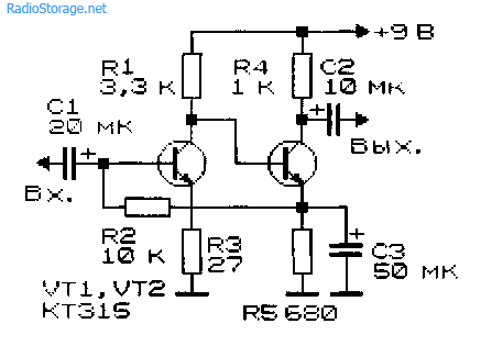
Figure: 13. Two-stage low-frequency amplifier on KT315 transistors - option 2.
The microphone amplifier (Fig. 11) is characterized by a low level of intrinsic noise and a high gain [MK 5/83-XIV]. An electrodynamic type microphone is used as a VM1 microphone.
A telephone capsule can also act as a microphone. Stabilization of the operating point (initial bias based on the input transistor) of the amplifiers in Fig. 11 - 13 is carried out due to the voltage drop across the emitter resistance of the second amplification stage.

Figure: 14. Two-stage ULF with a field-effect transistor.
The amplifier (Fig. 14), which has a high input impedance (about 1 MΩ), is made on a field-effect transistor VT1 (source follower) and a bipolar one - VT2 (with a common one).
A low-frequency cascade amplifier based on field-effect transistors, which also has a high input impedance, is shown in Fig. fifteen.

Figure: 15. circuit of a simple two-stage ULF on two field-effect transistors.
ULF circuits for working with a low-ohm load
Typical ULFs designed to operate on a low-impedance load and having an output power of tens of mW and higher are shown in Fig. 16, 17.

Figure: 16. Simple ULF to work with the inclusion of a load with low resistance.
The VA1 electrodynamic head can be connected to the amplifier output, as shown in Fig. 16, or in the diagonal of the bridge (Fig. 17). If the power source is made of two series-connected batteries (accumulators), the right output of the BA1 head according to the scheme can be connected directly to their midpoint, without capacitors СЗ, С4.

Figure: 17. Low-frequency amplifier circuit with the inclusion of a low-resistance load in the diagonal of the bridge.
If you need a circuit of a simple tube ULF, then such an amplifier can be assembled even on one lamp, look at our electronics website in the corresponding section.
Literature: Shustov M.A. Practical Circuitry (Book 1), 2003.
Corrections in the publication: in fig. 16 and 17 instead of diode D9, a chain of diodes is installed.